
Signal processing device, integrated circuit, control program, and computer readable recording medium

a technology of signal processing and integrated circuit, which is applied in the direction of color television details, instruments, television systems, etc., can solve the problems of deterioration of image and sound quality, noise components, and weak electrical fields used in analog television broadcasting, and achieve the effect of reducing the voltage of the target signal

Inactive Publication Date: 2014-04-01
SHARP KK
View PDF11 Cites 0 Cited by
  • Summary
  • Abstract
  • Description
  • Claims
  • Application Information

AI Technical Summary

Benefits of technology

The present invention is a signal processing device that reduces noise in an input signal. It includes multiple noise reduction units that cascade-connect to each other. Each unit samples the input signal and selects a representative target signal. The device determines the voltage difference between the target signal and the sampled signals. It then adjusts the voltage of the target signal based on the difference, effectively reducing the noise. The noise reduction units cause the noise components to be concentrated in higher frequencies, making them easier to filter out. This results in a cleaner output signal compared to conventional methods.

Problems solved by technology

This is because electric fields used in the analog television broadcasting are generally weak.
Similarly, even in a case where an analog video is converted into a digital video and rebroadcast, noise components are mixed in an image signal.
Noise components cause deteriorations in image and sound quality.
However, use of the median filter reduces even those signal components of an image signal which are small in amplitude.
This makes it possible to cause decreases in amplitude of noise components mixed in the input signal.

Method used


Image

  • Signal processing device, integrated circuit, control program, and computer readable recording medium
  • Signal processing device, integrated circuit, control program, and computer readable recording medium
  • Signal processing device, integrated circuit, control program, and computer readable recording medium

Examples


embodiment 1

[0061]Embodiment 1 of the present invention is described below with reference to FIGS. 1 through 9. A signal processing device (integrated circuit) 201 of Embodiment 1 is referred to as a signal processing device 201a.

[0062](Brief Description of Configuration of Signal Processing Device)

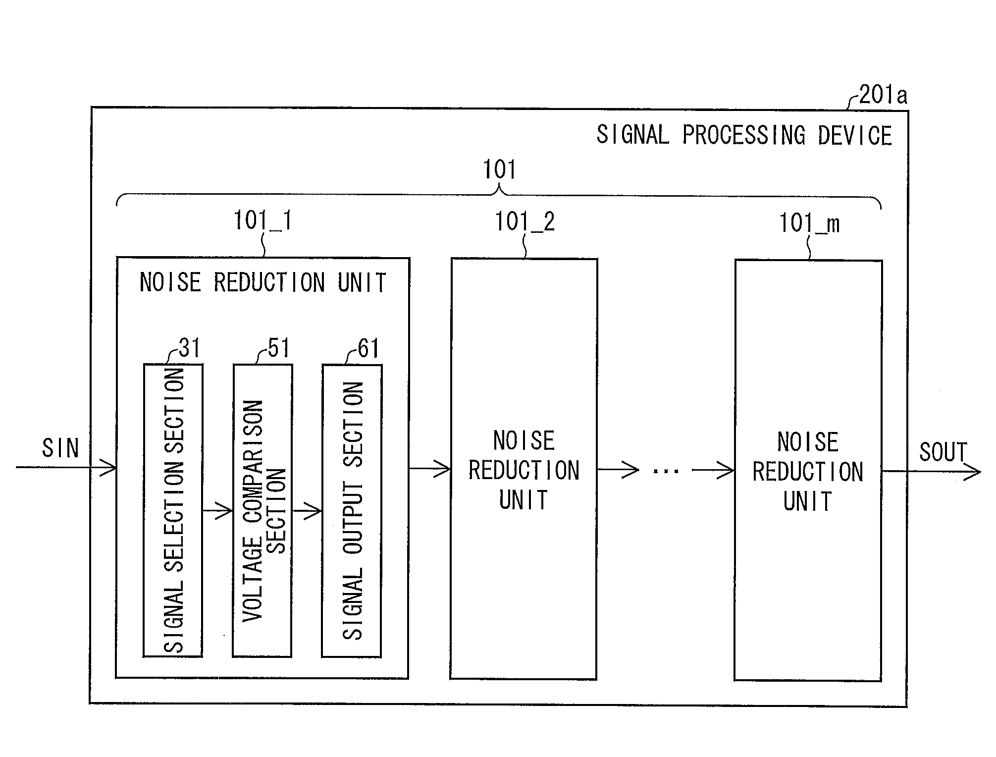
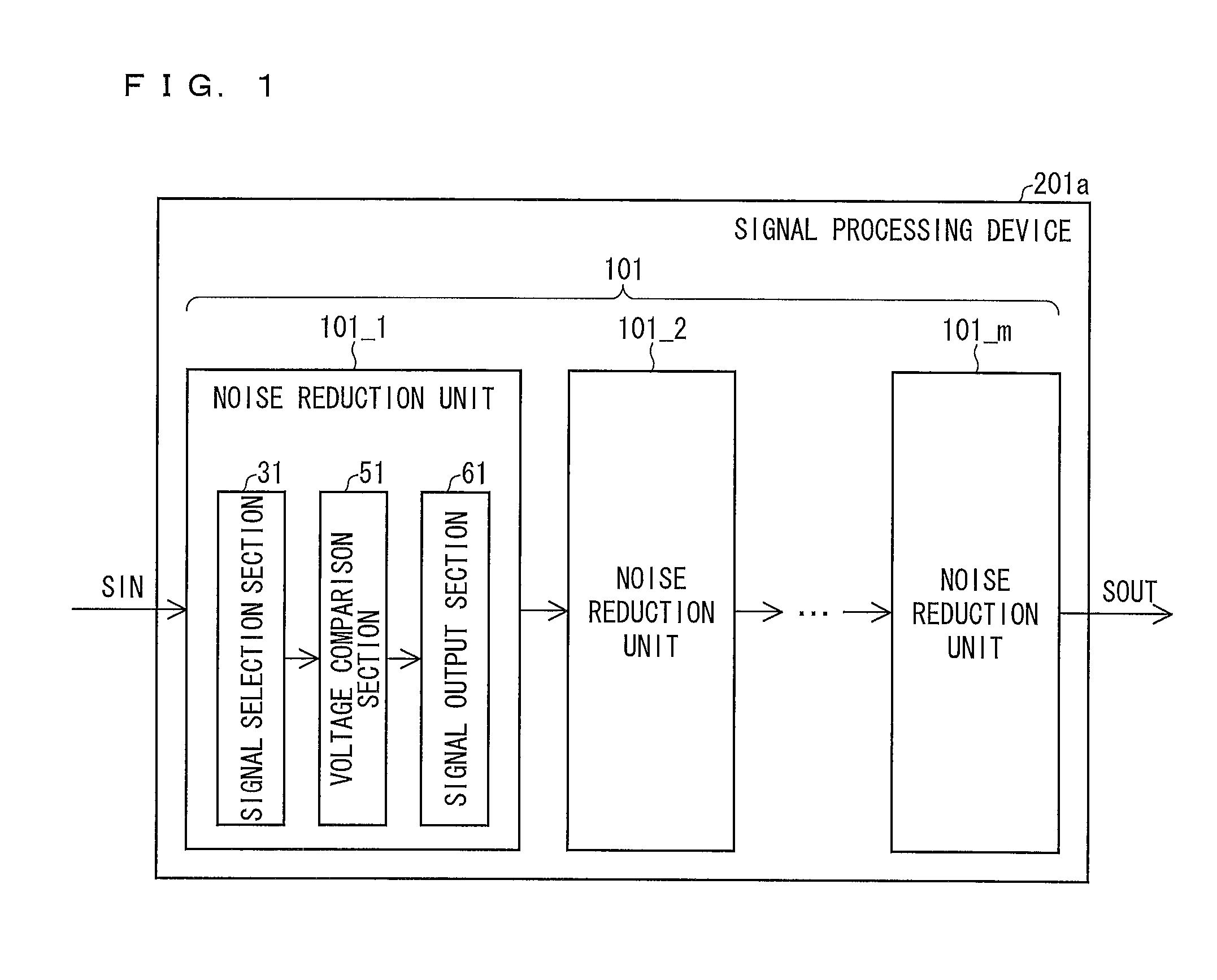
[0063]With reference to FIG. 1, the following description will schematically discuss how the signal processing device 201a is configured. FIG. 1 is a block diagram schematically illustrating how the signal processing device 201a is configured. As illustrated in FIG. 1, the signal processing device 201a includes noise reduction units 101—k (k=1, 2, . . . m) (where m is a positive integer of 2 or greater) which are cascade-connected to each other.

[0064]A noise reduction unit 101_1 is provided on a most upstream side of cascade-connected noise reduction units 101—k, and a noise reduction unit 101—m is provided on a most downstream side of the cascade-connected noise reduction units 101—k. An input sign...

embodiment 2

[0121]Embodiment 1 has discussed the noise reduction unit 101 including the signal selecting units 31 in which the first and second tap numbers are equal to each other. The present invention is, however, not limited to this. Embodiment 2 will discuss a signal processing device 201 in which noise reduction units, each of which includes a signal selection section whose first and second tap numbers are not equal to each other, are cascade-connected to each other.

[0122]A noise reduction unit, which includes a signal selection section whose first and second tap numbers are not equal to each other, unsymmetrically reduces noise components in first and second regions, which are divided by an edge in an image, which edge serves as a boarder between the first and second regions. Note, however, that since there is no correlation between noise components and an image signal, such an unsymmetrical reduction in the noise components causes no problem.

[0123]Embodiment 2 will be described below wit...

modification example

[0186]Embodiment 1 has described the signal processing device 201a in which only the noise reduction units 101 are cascade-connected to each other. Embodiment 2 has described the signal processing device 201b in which only the noise reduction units 102 are cascade-connected to each other. Note, however, that the signal processing device 201 is neither limited to the configuration of the signal processing device 201a nor limited to the configuration of the signal processing device 201b. For example, the signal processing device 201 can be configured so that one or more noise reduction units 101 and one or more noise reduction units 102 are mixed and cascade-connected to each other.

Reference Embodiment

[0187]Note that the noise reduction unit 102 described in Embodiment 2 alone can bring about an effect similar to the noise reduction effect brought about by the signal processing device 201a described in Embodiment 1. This is described with an example configuration of the signal process...


PUM


Abstract

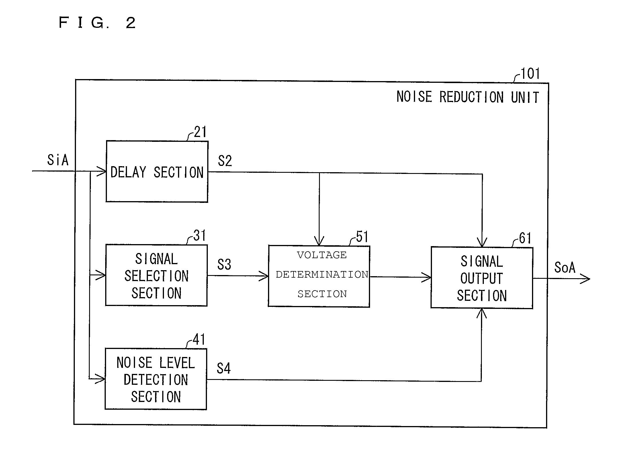
A signal processing device (201) includes noise reduction units (101), cascade-connected to each other, each of which includes: a signal selection section (31) for selecting a representative value from sampled signals obtained from an input signal by sampling a target signal and signals which are away from the target signal by given intervals; a voltage determination section (51) for determining which of a determined representative value and a voltage of the target signal is larger; and a signal output section (61) for increasing or decreasing the voltage of the target signal depending on a result of the determining and outputs the target signal as the output signal. A combination of intervals between the target signal and the signals excluding the target signal vary from noise reduction unit (101) to noise reduction unit (101). A noise reduction unit on a more upstream side has a larger maximum value of the intervals.

Description

TECHNICAL FIELD[0001]An image signal or an audio signal has a noise while imaging or recording is carried out. The present invention relates to a signal processing device for reducing noise components mixed in a signal.BACKGROUND ART[0002]Conventionally, while imaging or image data transmitting is being carried out, noise components (noise) such a so-called snow noise, Gaussian noise, or shot noise are mixed in an image signal. For example, in analog TV broadcasting, noise components are mixed in an image signal while the image signal is being transmitted. This is because electric fields used in the analog television broadcasting are generally weak. Similarly, even in a case where an analog video is converted into a digital video and rebroadcast, noise components are mixed in an image signal. Note that this is also true for audio recording or audio data transmitting.[0003]Noise components cause deteriorations in image and sound quality. In order to prevent such deteriorations in ima...

Claims


Application Information

Patent Timeline
Patent Type & Authority Patents(United States)
IPC IPC(8): G06K9/40H04N5/21H04N5/217G06K9/48H04N5/00
CPCH04N5/21H04N5/213
Inventor GOHSHI, SEIICHINUMAO, TAKAJIMINE, TAKASHI
Owner SHARP KK
Learn More