
Rectifier and high efficiency charge pump for RFID

a charge pump and rectifier technology, applied in the field of rectifiers and charge pumps, can solve the problems of significant power loss in the rectifiers, and achieve the effects of reducing resistive losses and leakage losses of the transistor, increasing output voltage, and increasing the read range of the rfid tag

Active Publication Date: 2014-04-01
NXP BV
View PDF13 Cites 11 Cited by
  • Summary
  • Abstract
  • Description
  • Claims
  • Application Information

AI Technical Summary

Benefits of technology

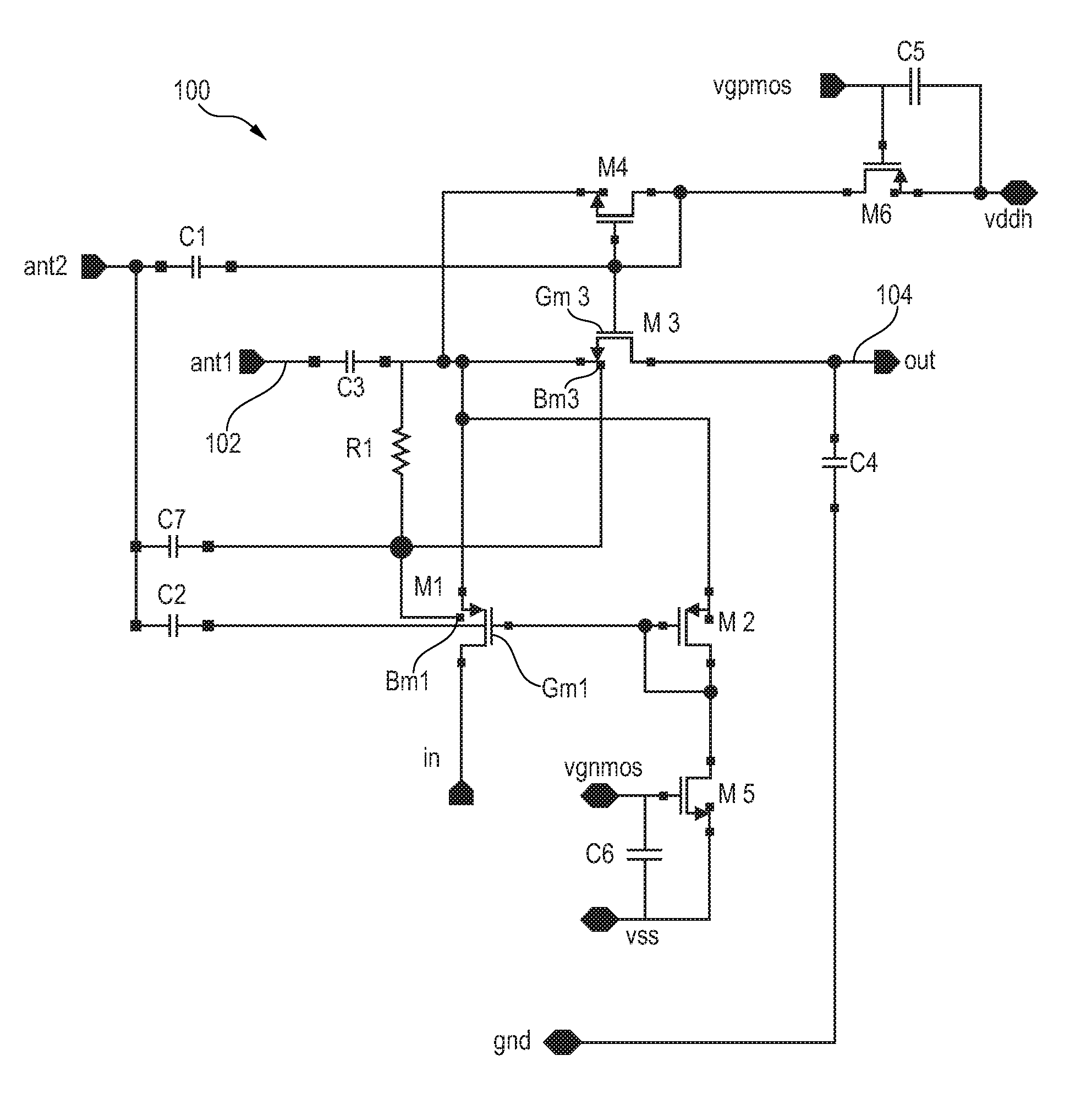
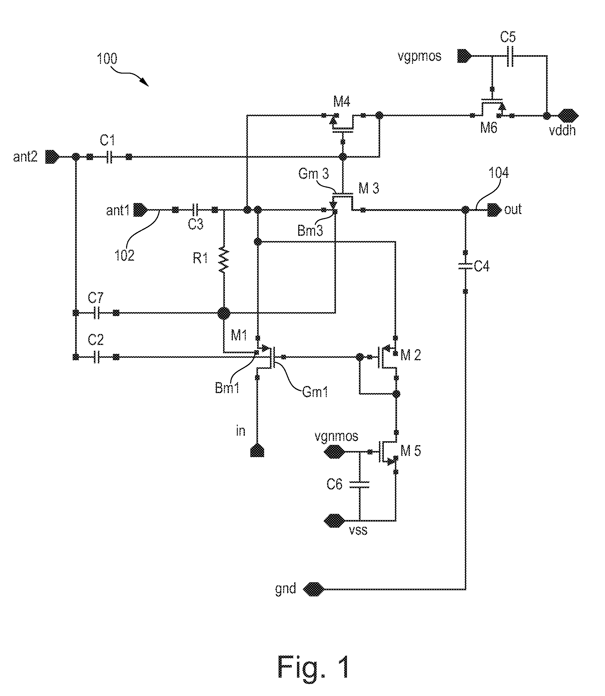
[0007]According to a first aspect of the invention there is provided a rectifier, comprising an AC input for receiving an AC input signal, a DC output, at least one transistor for providing a rectified output signal to the DC output wherein the transistor is a field effect transistor, and a threshold changing circuit coupled to the bulk of the transistor, the threshold changing circuit being adapted for electrically biasing the bulk of the transistor depending on the AC input signal to thereby change the voltage threshold of the transistor depending on the AC input signal. This allows for a dynamic adaption of the voltage threshold of the transistor to the AC input signal.
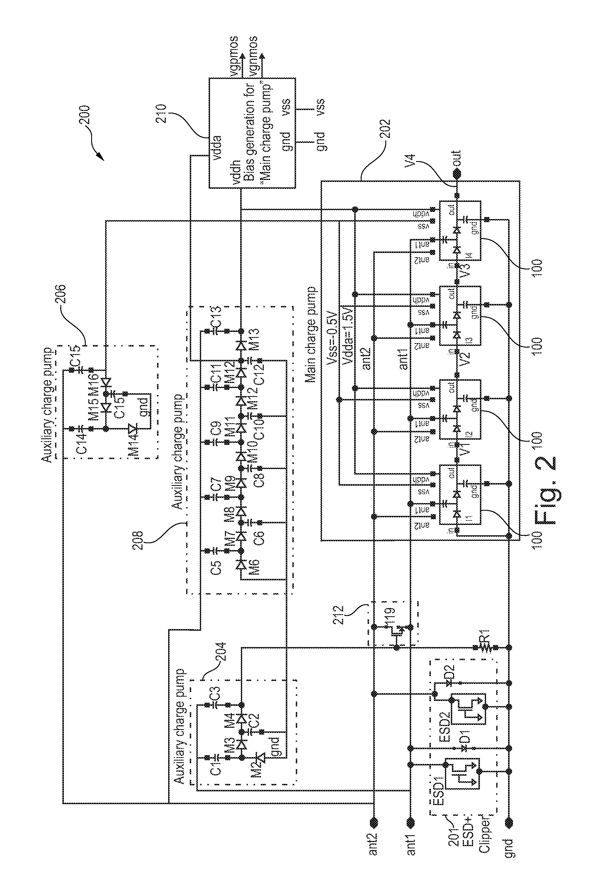
[0024]According to an embodiment of the fourth aspect, the method comprises automatically tuning at least the imaginary part of the input impedance of the charge pump device so as to provide a maximum output voltage of the charge pump. By such a self-tuning of the charge pump, a high bandwidth may provided by the RFID device while also the Q factor of the charge pump need not to be limited. Higher Q factor helps to improve the power conversion efficiency (PCE) of the charge pump.

Problems solved by technology

The restricted quality factor results in a significant power loss in the rectifiers.

Method used


Image

  • Rectifier and high efficiency charge pump for RFID
  • Rectifier and high efficiency charge pump for RFID
  • Rectifier and high efficiency charge pump for RFID

Examples


Embodiment Construction

[0043]The illustration in the drawings is schematic. It is noted that in different figures, similar or identical elements are provided with the same reference signs.

[0044]In the following, aspects, examples and embodiments of the herein disclosed subject matter are illustrated for the exemplary use case of an RFID tag. With measures described herein, the efficiency of the charge pump can in particular be increased by operating the charge pump at a higher quality factor, while still meeting the bandwidth requirement using a novel self-tuning scheme to extend the bandwidth of the high-Q charge pump.

[0045]Key features of embodiments of the herein disclosed subject matter are:[0046]A high efficiency pMOSFET / nMOSFET rectification stage using dynamic threshold MOSFET. The idea is to use the input signal to reduce the threshold voltage when the transistor has to be on, and to increase the threshold when the transistor has to be off. This allows reducing both the resistive losses and the le...


PUM


Abstract

It is described a high efficiency rectification stage using dynamic threshold MOSFET. The idea is to use the input signal to reduce the threshold voltage when the transistor has to be on, and to increase the threshold when the transistor has to be off. This allows reducing both the resistive losses and the leakage current. A matching network allows the generation of a second higher voltage signal to drive the control gates and the bulk, i.e. the wells, of the transistors. Further, a self-tuned front-end is provided to extend the bandwidth of the high-Q charge pump.

Description

[0001]This application claims the priority under 35 U.S.C. §119 of European patent application no. 10174356.5, filed on Aug. 27, 2010, the contents of which are incorporated by reference herein.FIELD OF THE INVENTION[0002]The present invention relates to the field of rectifiers and charge pumps.BACKGROUND OF THE INVENTION[0003]RFID tag and reader systems may operate over a wide range of frequencies, including low-frequency (LF) applications, high-frequency (HF) applications, and ultra-high-frequency applications (UHF). LF applications typically operate from 125-148.5 kHz. HF applications typically operate at 13.56 MHz. UHF applications typically operate from 300 MHz to 3 GHz. The “read range” of an RFID tag and reader system is often defined as the distance from which a reader can communicate with a tag. Passive LF and HF applications offer very short read ranges, often requiring the RFID tag to be within 0.01 to 0.5 m of a reader for successful communication. Passive UHF applicatio...

Claims


Application Information

Patent Timeline
Patent Type & Authority Patents(United States)
IPC IPC(8): H02M7/217
CPCH02M3/07H02M7/217
Inventor EL, WAFFAOUI, RACHID
Owner NXP BV
Learn More