Method of relayed wireless transmission
- Summary
- Abstract
- Description
- Claims
- Application Information
AI Technical Summary
Benefits of technology
Problems solved by technology
Method used
Image

Examples
Embodiment Construction
[0021]Some embodiments of the invention will now be described, by way of example, with reference to the accompanying drawings.
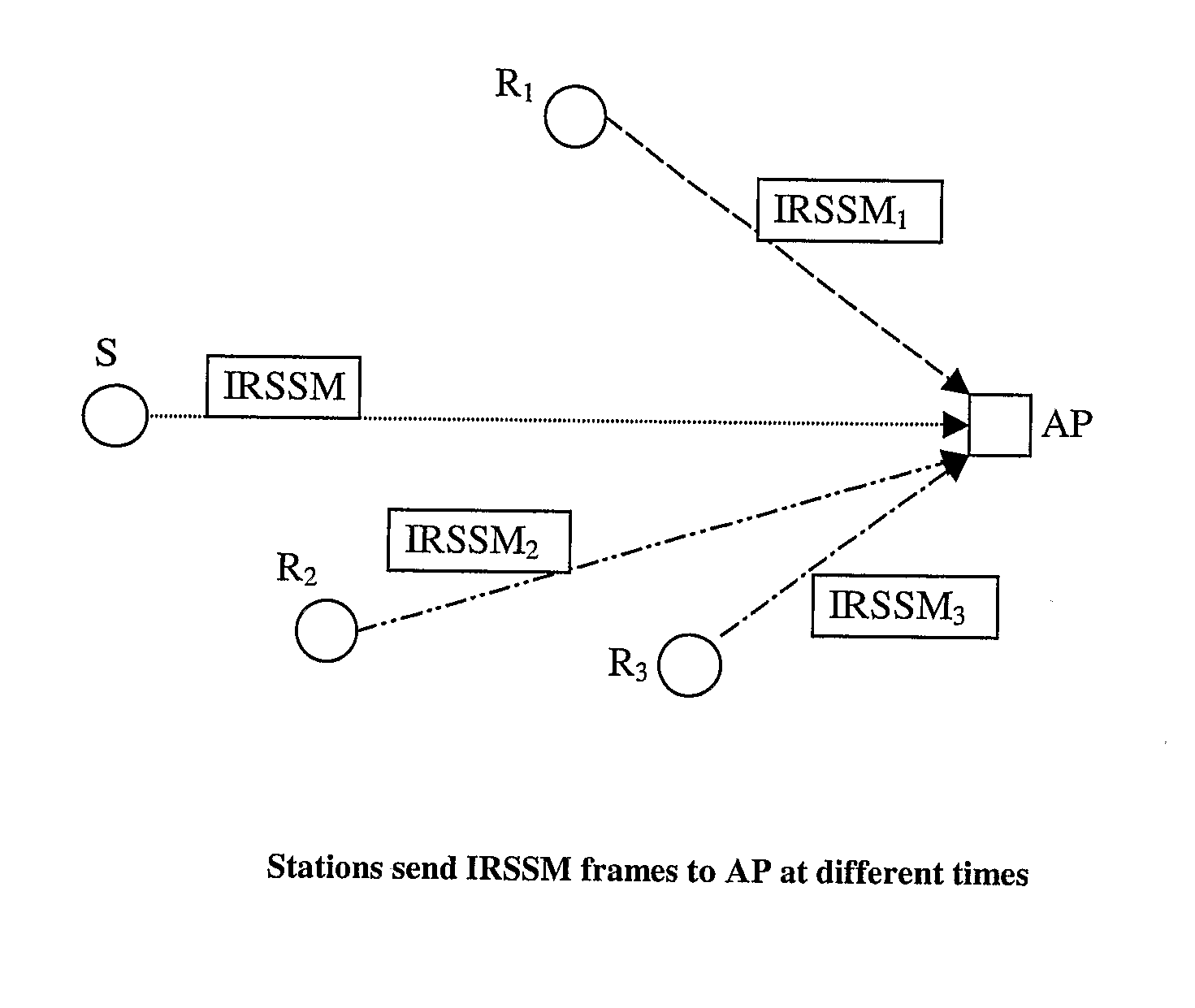
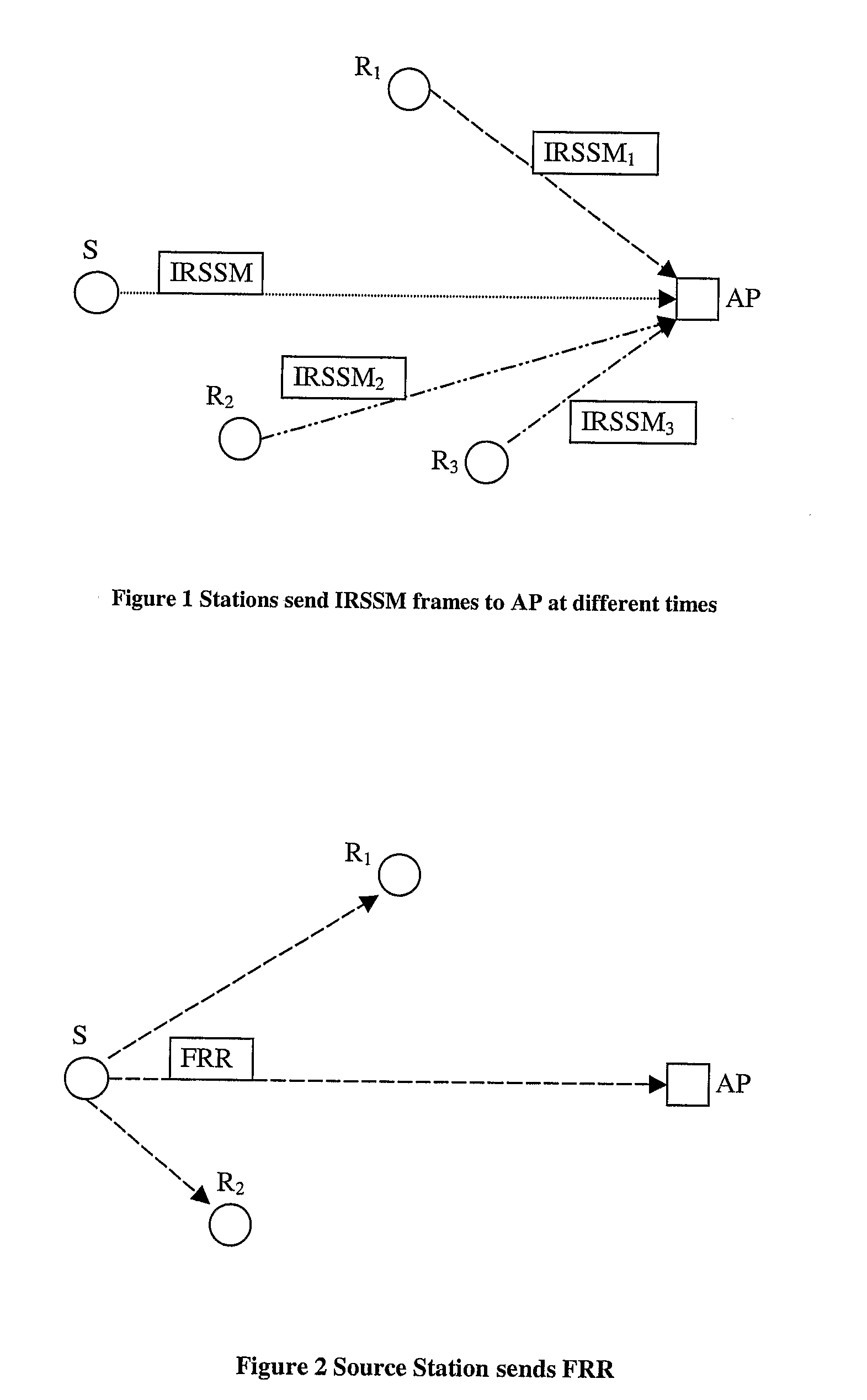
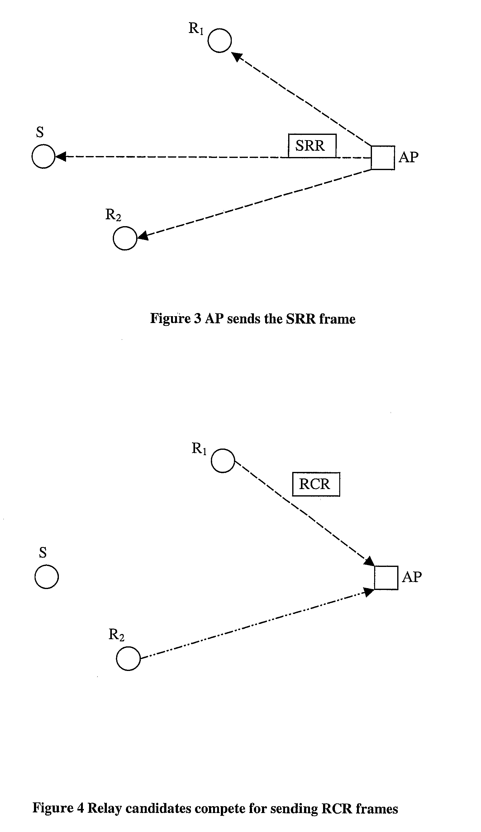
[0022]FIG. 1 is a schematic diagram of a wireless LAN operating according to the IEEE 802.11 standard. A base station, or access point, AP is provided, and has a radio transceiver which communicates with a radio transceiver in each of a number of terminal devices S (only one of which is, however, shown in the drawing). Also shown are relay stations R1, R2, R3. When conditions are poor, a device S (referred to as source, may transmit via a relay to the AP, rather than directly, in order to obtain a stronger signal and hence a higher data rate. In this version, the relays are dedicated relay stations, but the relay functionality could, if desired, be provided in the terminal devices S.
[0023]There is a strong correlation between path loss and the achievable transmission rate for sending data. Both distance and obstacles produce fading effects that contribute to ...
PUM
 Abstract
Description
Claims
Application Information
PatSnap Eureka turns technology decisions into work you can execute. Powered by our Innovation Knowledge Graph, it runs expert workflows across engineering, life sciences, materials and intellectual property. Get your review-ready output in minutes.


