
System, method, and computer program product for connecting or coupling analog audio tone based communications systems over a packet data network

a packet data network and communication system technology, applied in data switching networks, multiplex communication, frequency-division multiplex, etc., can solve problems such as data errors, application being run over the link, and being much more susceptible to noise and small disturbances on the lin

Active Publication Date: 2014-04-01
NSGDATACOM
View PDF91 Cites 227 Cited by
  • Summary
  • Abstract
  • Description
  • Claims
  • Application Information

AI Technical Summary

Problems solved by technology

Higher speed modems also use Phase Shift Keying (PSK) or Quadrature Amplitude Modulation (QAM) but depend on a high quality audio connection and are much more susceptible to noise and small disturbances on the line than is FSK.
At the receiving end of a modem link any break in signal or short-term distortion in signal quality may result in data errors from which the application being run over the link may not recover.
Often a modem is embedded in an expensive end device and cannot be bypassed without replacing the whole unit, for example in an ATM machine or in a Commercial HVAC system.
In this mode of operation the packet network effectively performs exactly the same functions as a standard digital telephone network, the primary difference being that the packet network introduces a substantial transmission delay that varies from packet to packet.
Buffers in the end-point routers may absorb jitter to some extent, but there is always a trade-off between the magnitude of jitter that can be absorbed and the delay that can be tolerated by the applications running over the network.
For many applications the delay and jitter of an IP network can exceed the operational response and timeout limitations of the attached systems and modem passthrough will not operate successfully, even for low data rate modems.
Additionally, any significant packet loss during the call is likely to be fatal to the transmission.
The problem is particularly acute where the packet network experiences relatively long delays, such as over satellite links, or where there is a wide variation in delay and a possibility of packet loss, such as with some wireless data services.
However many VoIP devices also compress the G.711 data to minimize the amount of data sent over the packet network, which may typically reduce the delay and jitter experienced.
All commonly used VoIP compression algorithms function by discarding information during the compression process with the result that the audio signal output at the receiving end of the link is a distortion of the input audio signal to some extent.
As a result, the decoders of analog modems normally cannot decode signals that have been transmitted over VoIP systems that use compression.
Even the very slowest DTMF and FSK modems do not operate when an attempt is made to use Modem Passthrough over a VoIP network with voice compression enabled.
Nevertheless, the operational response and timeout limits of an application may cause a Modem Relay communication to fail, simply due to the unavoidable delay and jitter introduced by the use of the packet data network.
However IP networks, and cellular wireless data networks in particular, are not geared to support the transportation of frequency and phase sensitive communications signals or to supporting an analog system with critical timing windows, with the result that the conventional techniques of modem passthrough and modem relay do not work successfully for many such applications.

Method used


Image

  • System, method, and computer program product for connecting or coupling analog audio tone based communications systems over a packet data network
  • System, method, and computer program product for connecting or coupling analog audio tone based communications systems over a packet data network
  • System, method, and computer program product for connecting or coupling analog audio tone based communications systems over a packet data network

Examples


exemplary embodiment 300

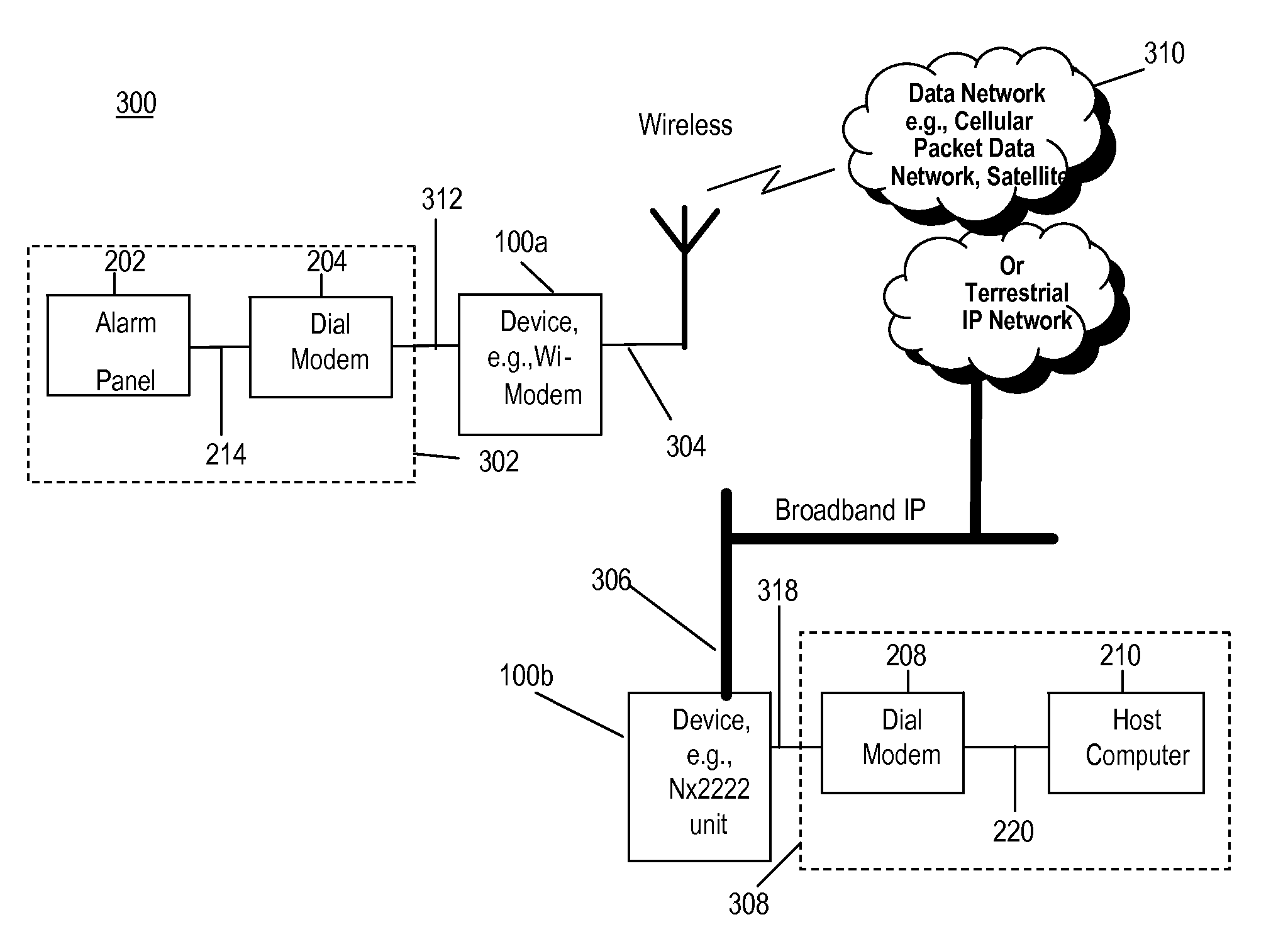
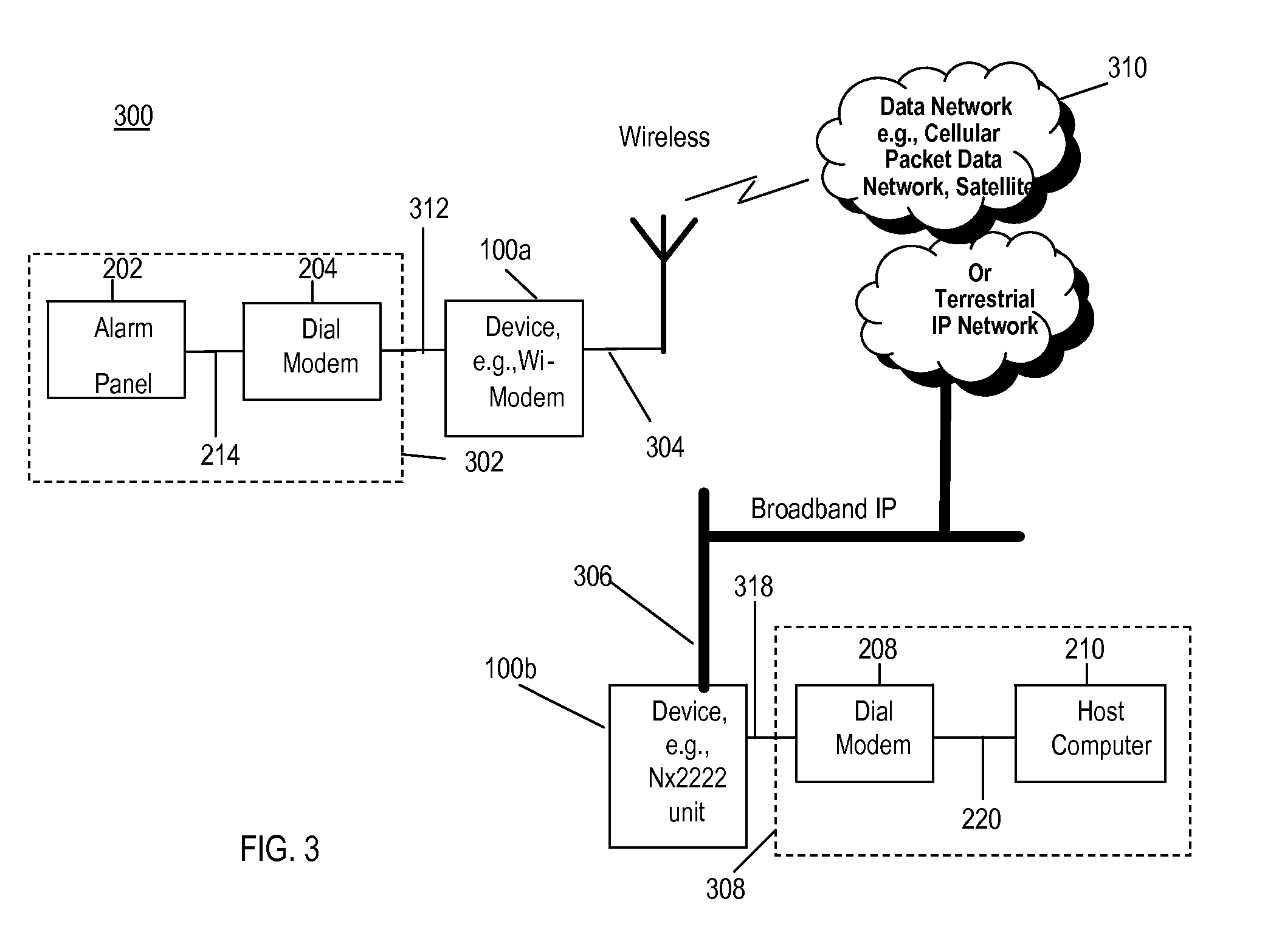
[0105]In exemplary embodiments, analog modem tones may be transmitted from the alarm system 202 circuits of exemplary network 214, across link 312 to exemplary device 100a. Here, in exemplary device 100a the analog tones may be decoded and the decoded symbols transmitted over network links 304 and 306 to the second exemplary device 100b. Symbols received by the second exemplary device 100b may be converted into modem tones for transmission to the exemplary host 210 over network 220 of alarm monitoring center 308. In exemplary embodiment 300, the link 318 between exemplary device 100 and the alarm monitoring center 210, may be a digital T1 / E1 connection capable of supporting multiple simultaneous calls, or a single analog connection, which persons skilled in the art will recognize as being functionally equivalent for the current purpose.

[0106]In exemplary embodiments, analog modem tones may be transmitted from the alarm monitoring center 308 of exemplary network 220, across link 318 ...

exemplary embodiment 500

[0266]Referring to FIG. 5, in an exemplary embodiment 500, device 100c provides the ability to receive VoIP packets directly, such as, for example, but not limited to from a VoIP service provider, and act as a VoIP gateway converting these packets to PSTN 206 compatible signals (not illustrated), or as illustrated, receive the regenerated audio signal directly from the PSTN 206 as an analog line or a TDM link. While exemplary attributes such as VoIP and compression may be described, the foregoing terminology is employed for illustrative purposes only and is in no way to be construed as limitations of the present embodiments.

[0267]Referring to FIG. 5, in an exemplary embodiment, operation of the TRANSMITTER 302 and RECEIVER 308 systems may be identical to the descriptions already given with reference to FIG. 3. In the exemplary embodiment of FIG. 5, an audio signal received by the device 100c across the network 500 (including 506, 508, 206, and 510) may have been compressed and decom...


PUM


Abstract

An automated telecommunications system includes a first system operable to receive PSTN compatible audio frequency signals, to decode and interpret said incoming signals according to the message format and a modem protocol being used, and transmit digital messages to a second system over a packet data network. Said second system receives and interprets digital messages incoming from the first system, encodes and regenerate outgoing audio frequency signals. The system may be bi-directional and operate over a packet based data network, such as for example an Internet protocol (IP) based network, a satellite based network, or an IP based cable or wireless network. The functionality of said first and second systems may be combined at a single location and operate with a VoIP network to allow modem signals to pass across the VoIP system.

Description

CROSS-REFERENCE TO RELATED APPLICATIONS[0001]This application is a continuation-in-part of U.S. patent application Ser. No. 11 / 952,818, filed Dec. 7, 2007, and of common inventorship and assignee, the contents of which is incorporated herein by reference in its entirety. This application also has common inventorship and is of common assignee to U.S. patent application Ser. No. 12 / 270,697, filed Nov. 13, 2008, the contents of which is incorporated herein by reference in its entirety.BACKGROUND OF INVENTION[0002]1. Field of the Invention[0003]The present invention relates generally to the transmission of analog audio tone based communications, and more particularly to such transmission over a packet data network.[0004]2. Related Art[0005]Many older ‘legacy’ telecommunications systems use dial-up telephone lines with analog modems to send data between equipment and digital computer systems. The modulator of a modulator / demodulator (modem) at one end of the telephone line converts digit...

Claims


Application Information

Patent Timeline
Patent Type & Authority Patents(United States)
IPC IPC(8): H04J3/16
CPCH04L45/22H04L45/28H04W4/18H04L41/06H04L12/24H04W24/04H04L41/00
Inventor KING, GRAHAM
Owner NSGDATACOM
Learn More