Secondary combustion system for reducing the level of emissions generated by a turbomachine

a turbomachine and emission reduction technology, applied in the field of combustion systems, can solve the problems of significant nox formation, high operational cost, and significant energy consumption of some turbines and combustion hardware, and achieve the effect of reducing a level of emissions

Active Publication Date: 2014-04-08
GENERAL ELECTRIC CO
View PDF37 Cites 20 Cited by
  • Summary
  • Abstract
  • Description
  • Claims
  • Application Information

AI Technical Summary

Benefits of technology

[0009]In accordance with an embodiment of the present invention, a method of reducing a level of emissions generated by a system, the method comprising: providing a combustion system for generating power, wherein the combustion system comprises: a primary combustion system comprising at least one primary fuel nozzle that generates a stream of combustion products; a secondary combustion system located downstream of the primary combustion system; wherein the secondary combustion system comprises at least one injector for delivering a fluid into the stream of combustion products; providing an airstream, wherein the airstream supplies air to the primary combustion system and the secondary combustion system; apportioning the fuel between the primary combustion system and the secondary combustion system.

Problems solved by technology

However for some turbomachines, the required temperature of the generate combustion products entering the first stage turbine nozzle, at some load, requires operation at peak gas temperature in the reaction zone.
Peak operation typically exceeds the thermal NOx formation threshold temperature resulting in significant NOx formation even though the fuel and air are in a lean premixed form.
An active cooling system may be considered a parasitic load on the output of the turbomachine; and consumes a significant amount of energy and requires operational costs.
Some LDI systems may not uniformly distribute the injected fuel and air mixture, which may lead to local high-NOx regions and cause hot streaks on some turbine and combustion hardware.
Here, the position of the injectors may be fixed and not allow for adjustment.

Method used


Image

  • Secondary combustion system for reducing the level of emissions generated by a turbomachine
  • Secondary combustion system for reducing the level of emissions generated by a turbomachine
  • Secondary combustion system for reducing the level of emissions generated by a turbomachine

Examples


Embodiment Construction

[0024]Certain terminology is used herein for convenience only and is not to be taken as a limitation on the invention. For example, words such as “upper,”“lower,”“left,”“front”, “right,”“horizontal,”“vertical,”“upstream,”“downstream,”“fore”, and “aft” merely describe the configuration shown in the Figures. Indeed, the components may be oriented in any direction and the terminology, therefore, should be understood as encompassing such variations unless specified otherwise.

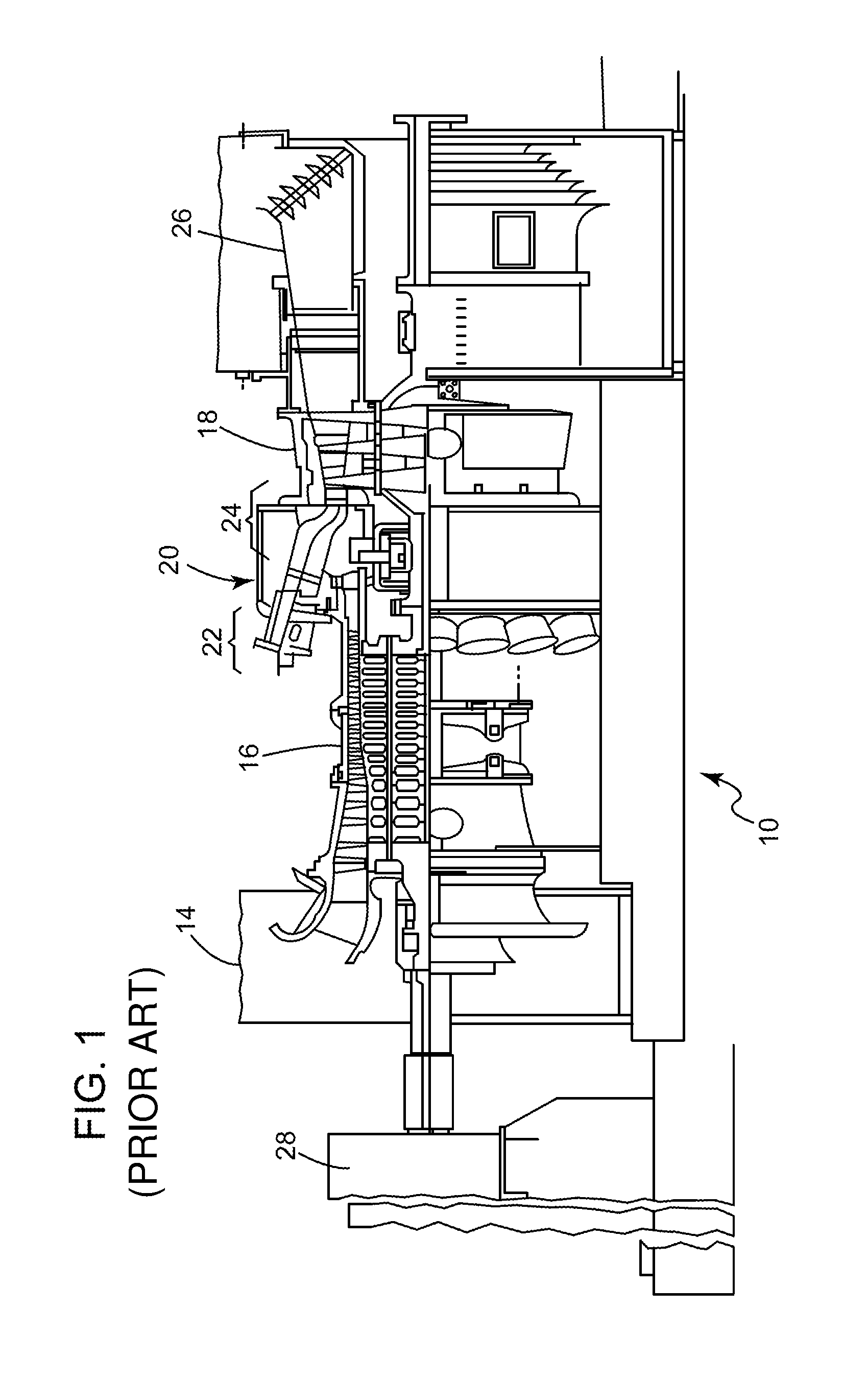
[0025]The following discussion focuses on an embodiment of the present invention integrated with a turbomachine, such as, but not limiting of, a gas turbine. Other embodiments of the present invention may be integrated with other combustion systems that operators may desire a reduction the level of emissions. For example, but not limiting of, the other combustion systems may include a kiln, a furnace, a fired boiler, or the like.

[0026]An embodiment of the present invention provides a method of operating a combustion...


PUM


Abstract

An embodiment of the present invention provides a method and system of operating a combustion system that has Lean direct injection (LDI) functionality. The method and system provides a passive cooling system for an injector of the LDI system. The method and system may also provide a means to direct the flow of the fluid exiting the injector of the LDI system.

Description

BACKGROUND OF THE INVENTION[0001]This invention relates generally to a combustion system and, more specifically, to a combustion system that comprises a primary reaction zone; and a secondary reaction zone, which includes an injector for injecting a fluid into a stream of combustion products generated within the primary reaction zone.[0002]Generally, some combustions systems produce mechanical torque by combusting a fuel and air mixture. This process yields by-products including undesired emissions. Some combustion systems form an essential part of a turbomachine, such as, but not limiting of, a gas turbine. The primary emissions are oxides of nitrogen (NOx), carbon monoxide (CO), and unburned hydrocarbons (UHC). Oxidation of molecular nitrogen in air breathing machines, such as, but not liming of, gas turbines, is highly dependent upon the maximum temperature in the combustion system reaction zone and the residence time for the reactants at the maximum temperatures reached within t...

Claims


Application Information

Patent Timeline
Patent Type & Authority Patents(United States)
IPC IPC(8): F02C1/00
CPCF23N2037/02F05D2270/082F23R3/346F23N2041/20F23R3/06F23N2037/32F23R3/283F23N5/003F02C7/228F23N1/002F23N2237/32F23N2237/02F23N2241/20
Inventor KRAEMER, GILBERT O.BERRY, JONATHAN D.KEYSER, RICHARD F.
Owner GENERAL ELECTRIC CO
Why Eureka
Try Eureka