Illumination of diffusely scattering media

a diffuse scattering and sample technology, applied in the field of diffuse scattering sample illumination, can solve the problems of difficult to obtain a sufficiently high signal to noise ratio for spectral features of interest, small cross section of raman scattering, and limited incident light intensity, so as to minimise the escape of backscattered light and maximize the return of incident light

Active Publication Date: 2014-04-08
AGILENT TECH LDA UK LTD
View PDF14 Cites 6 Cited by
  • Summary
  • Abstract
  • Description
  • Claims
  • Application Information

AI Technical Summary

Benefits of technology

[0008]The invention provides a method of increasing the illumination of a diffusely scattering sample by a beam of incident light, such as a laser beam or other substantially monochromatic beam of light, by covering a region of the sample with a delivery filter, and directing the beam to the sample through the filter. The filter has characteristics such that the light at the incident light wavelength which is diffusely scattered back from the sample to the filter at a wider range of angles of incidence than the incident beam is preferentially reflected back to the sample. Effectively, the filter acts as a unidirectional mirror, preventing loss of incident wavelength light, especially at the critical point of application to the sample of the incident light beam where intensities are greatest.
[0010]An example delivery filter is a narrow band pass filter with a band pass region matching the incident light wavelength, to transmit the incident beam at normal incidence, but which increasingly reflects light of the same wavelength at larger angles of incidence. The same effect can be achieved using a notch filter or short wavelength transmission edge filter, having a reflection or low transmission region which lies just above the incident wavelength for normal incidence, but which shifts to cover the incident wavelength at larger angles of incidence.
[0016]The delivery filter is preferably positioned adjacent to the sample, to maximise the return of incident light to the sample, and minimise escape of backscattered light around the edges of the filter. For example, if the filter has a diameter “d” then it may preferably be positioned within one diameter distance d from the sample, and more preferably half a diameter d / 2, or more preferably still within a distance of about d / 10. In practice, it may be preferable to locate the filter as close as possible to, for example touching, the sample. Typically, the filter may be parallel or approximately parallel to the underlying sample surface. Light may be collected by transmission back through the delivery filter, for example by using a filter having a transmission region covering the spectral features of interest, as discussed in detail below. Alternatively, a separate collection filter could be used having a suitable transmission region which preferably excludes the wavelength of the incident light for a wide range of angles of incidence.

Problems solved by technology

The cross section for Raman scattering is, however, particularly small, and obtaining a sufficiently high signal to noise ratio for spectral features of interest is challenging, especially in applications outside of the laboratory in which less sensitive equipment may be used.
In many practical applications, incident light intensity must be limited, for example to avoid damage to living tissue, and exposure times may also be limited, for example on a production line, or where a measurement must be taken from a human patient in a reasonably short length of time.
Of course, these and similar constraints also apply in the case of various types of infrared and other spectroscopic techniques.

Method used


Image

  • Illumination of diffusely scattering media
  • Illumination of diffusely scattering media
  • Illumination of diffusely scattering media

Examples


Embodiment Construction

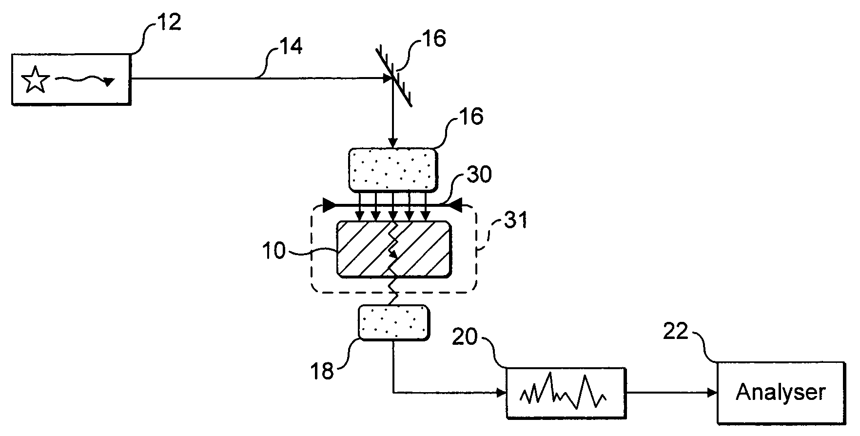
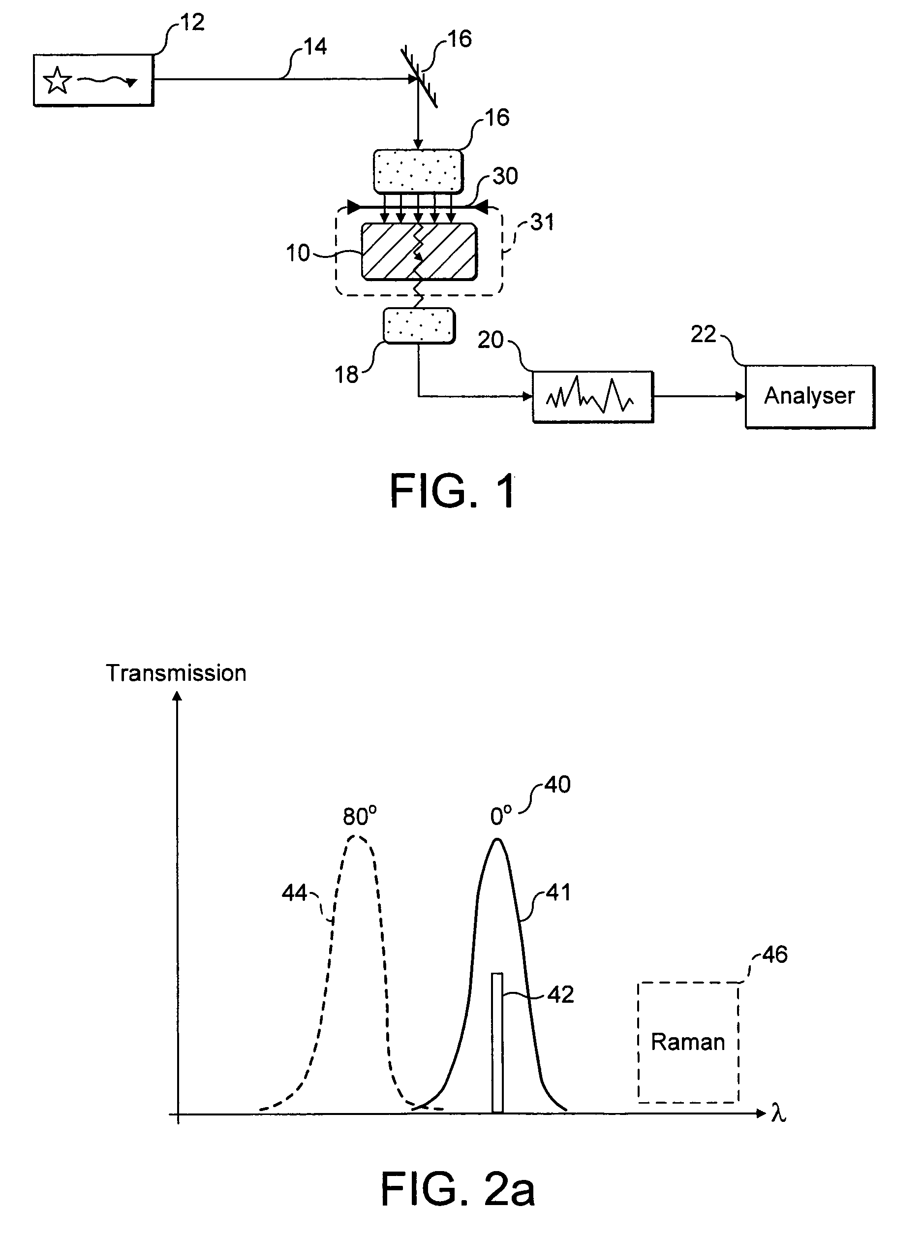
[0037]Referring to FIG. 1 there is shown, schematically, apparatus for determining characteristics of a diffusely scattering or turbid sample 10 using spectroscopy. In this particular example transmission Raman spectroscopy is used, although other techniques such as infrared absorption or fluorescence spectroscopy could be used.

[0038]A laser 12 forms an incident beam (probe beam) of laser light 14 which is directed towards the sample 10 by delivery optics 16. The beam enters the sample, and after scattering within the sample some photons are collected by collection optics 18. One or more spectral components of the collected light are detected by detector 20, such as a spectrometer, and results of the detection may typically be passed to a computer or other analyser device 22 for data storage and / or interpretation. In particular, photons which have been inelastically Raman scattered to different wavelengths within the diffusely scattering sample may be detected and analysed.

[0039]For...


PUM

PropertyMeasurementUnit
angles of incidenceaaaaaaaaaa
threshold angleaaaaaaaaaa

Abstract

The invention provides a technique for increasing the illumination intensity of probe light in a diffusely scattering sample without increasing the power of the probe beam. Generally, an optical filter is used which permits a collimated probe beam of light to pass through to the sample, but which reflects back towards the sample much of the backscattered scattered probe light emerging at a wider range of angles. In particular embodiments a collimated laser beam is delivered to the sample through a multi-layer dielectric filter covering a portion of the sample. The filter is transmissive to the laser light at normal incidence, but reflective at shallower angles of incidence characteristic of the backscattered light.

Description

FIELD OF THE INVENTION[0001]The invention relates generally to the illumination of diffusely scattering samples. In particular, the invention relates to techniques for reducing loss of incident light from within a sample, so that intensity of the incident light within the sample is increased. The invention may, for example, be applied to spectroscopy to increase the intensity of spectral features to be detected.INTRODUCTION[0002]Various analytical applications involve the spectroscopic analysis of diffusely scattering media. Examples include the probing of living tissue to determine tissue parameters such as bone composition as discussed in WO2006 / 61565, breast tissue, or blood glucose composition. The spectroscopic analysis of pharmaceutical tablets may be used to determine crystalline states or purity on a production line, in post production testing, and when screening for counterfeits. Other applications include the laboratory analysis of a wide variety of powdered samples, turbi...

Claims


Application Information

Patent Timeline
Patent Type & Authority Patents(United States)
IPC IPC(8): G01N21/47G01N21/65G01J3/44
CPCG01J3/44G01N21/658G01N21/65G01N21/47G01N21/49G01J3/10G01N2021/4735G02B5/26
Inventor MATOUSEK, PAVEL
Owner AGILENT TECH LDA UK LTD
Why Eureka
Try Eureka