Permanent magnet, and method for manufacturing a permanent magnet

a permanent magnet and permanent magnet technology, applied in the field of permanent magnets, can solve the problems of relatively high cost of sintered magnet manufacturing, bonded magnets are generally not as efficient as sintered, etc., and achieve the effect of high magnetic strength

Active Publication Date: 2014-04-15
GRUNDFOS MANAGEMENT AS
View PDF19 Cites 2 Cited by
  • Summary
  • Abstract
  • Description
  • Claims
  • Application Information

AI Technical Summary

Benefits of technology

[0010]It is an object of the present invention to provide an advantageous permanent magnet without the described disadvantages and with higher magnetic strength. A further object is to provide an advantageous method for manufacturing a permanent magnet rotor.

Problems solved by technology

Disadvantages of using the mentioned magnets in rotors are that sintered magnets are generally relatively expensive to manufacture due to a complicated manufacturing process, and bonded magnets are generally not as efficient as sintered, e.g. due to their content of non-magnetic binder material.

Method used


Image

  • Permanent magnet, and method for manufacturing a permanent magnet
  • Permanent magnet, and method for manufacturing a permanent magnet
  • Permanent magnet, and method for manufacturing a permanent magnet

Examples


Embodiment Construction

[0099]Rotors comprising magnetic powder material are known in the art. Available permanent magnetic materials may comprise Ferrites, AlNiCo, SmCo, and NdFeB. Magnets made of these materials can be manufactured in many ways, but the most selected ways are sintering or bonding.

[0100]Sintering is a method for making objects from powder by heating the material until its particles adhere to each other. This heating process must be performed below the melting point of the powder material.

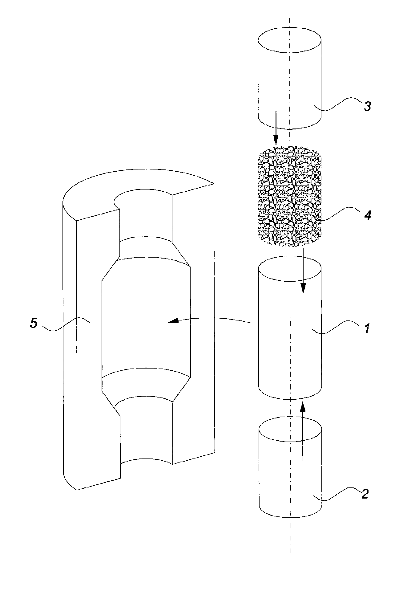
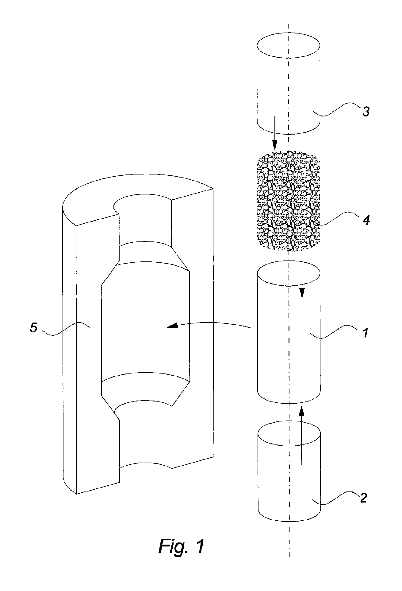
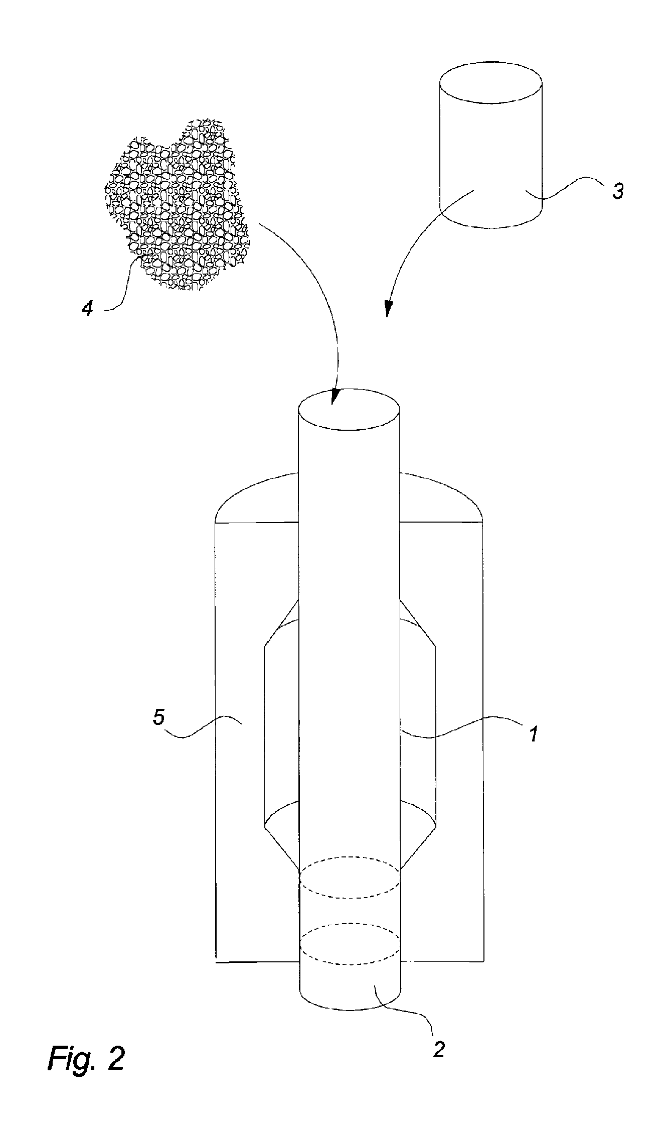
[0101]Compression bonded magnets are obtained by compressing a composite that involves a magnetic powder and a polymer binder, such as epoxy, in a mold with the desired size and shape.

[0102]One disadvantage of compression bonded magnets of the prior art is that the added binder has no magnetic effect, and therefore the possible strength of the magnet is reduced in relation to a magnet without binder.

[0103]One way to try to overcome this effect could be to mechanically compress the composite very hard. Unf...


PUM

PropertyMeasurementUnit
pressureaaaaaaaaaa
pressureaaaaaaaaaa
densityaaaaaaaaaa

Abstract

A permanent magnet, in particular a permanent magnet rotor for a machine, includes a first sleeve, a first cap and a second cap arranged to close off an inner opening of the first sleeve, and a permanent magnet material formed in the inner opening of the sleeve between the first cap and the second cap. The permanent magnet material is a compressed, non-bonded powder material including hard magnetic powder material, soft magnetic powder material, or a combination of hard and soft magnetic powder material. A method for manufacturing a permanent magnet rotor is also provided.

Description

CROSS-REFERENCE TO RELATED APPLICATIONS[0001]This application is a Section 371 of International Application No. PCT / EP2009 / 008897, filed Dec. 11, 2009, which was published in the English language on Jun. 17, 2010, under International Publication No. WO 2010 / 066455 A1 and the disclosure of which is incorporated herein by reference.BACKGROUND OF THE INVENTION[0002]The present invention relates to a permanent magnet and in particular to a permanent magnet rotor for an electric machine.[0003]The invention also relates to a method for manufacturing such a permanent magnet.[0004]In a preferred embodiment the permanent magnet according to the invention is a permanent magnet rotor for a machine.[0005]Many different types of permanent magnetic materials to be used in rotors are available on the market. Which material to select often depends on a balancing between the desired magnetic strength of the rotor and the price of the materials for the rotor, e.g. the magnetic powder. Furthermore, ma...

Claims


Application Information

Patent Timeline
Patent Type & Authority Patents(United States)
IPC IPC(8): H02K15/12
CPCH02K15/03H02K1/28Y10T29/49012
Inventor KJELDSTEEN, PETERSORENSEN, ALLAN IVO SOGAARDBENDIXEN, FLEMMING BUUS
Owner GRUNDFOS MANAGEMENT AS
Why Eureka
Try Eureka