Compact near eye display with scanned image generation

a near eye display and scanned image technology, applied in the field of near eye displays, can solve problems such as image degradation, and achieve the effect of limiting the overall size of the optics and minimizing the thickness of the display

Active Publication Date: 2014-04-15
VUZIX
View PDF7 Cites 73 Cited by
  • Summary
  • Abstract
  • Description
  • Claims
  • Application Information

AI Technical Summary

Benefits of technology

[0004]The invention, among its preferred embodiments, features a compact near eye display that generates image segments for a first dimension of an intended image and conveys an angular transform of the image segments along a waveguide toward a viewer's eye in a form that minimizes the thickness of the display in front of the viewer's eye and limits the overall size of the optics required to support the projection of virtual images into the viewer's eye. A scanning optic can be arranged to receive the angularly transformed image segments of the first dimension of the intended image and to angularly separate the transformed image segments in a second dimension of the intended image for propagation along the waveguide. The angularly distinguished image segments can be conveyed along the waveguide in a compact form to a position in front of a viewer's eye and an exit coupling of the waveguide can redirect the image segments into the viewer's eye as a virtual image.
[0009]The total number of angular positions through which the intended virtual image is scanned can be reduced by forming the pixel light source as multi-pixel source, such as a linear (one-dimensional) array generating one dimension of the intended image or a two-dimensional array generating at least portions of both dimensions of the intended image. The total number of angular scan positions can be reduced by a factor of the number of pixels generated by the pixel light source. The number of pixels generated is preferably fewer than the total number of pixels in the desired virtual image in at least one dimension of the array to reduce the size of the optics required for projecting the virtual image into the viewer's eye.

Problems solved by technology

Laser light is also prone to speckle, which can degrade the images.
These near eye displays with in-line scanning mirrors include large focusing optics for filling the mirrors and tend to be quite thick and otherwise cumbersome for mounting on viewers' heads as eyeglasses, headbands, or helmet attachments.

Method used


Image

  • Compact near eye display with scanned image generation
  • Compact near eye display with scanned image generation
  • Compact near eye display with scanned image generation

Examples


Embodiment Construction

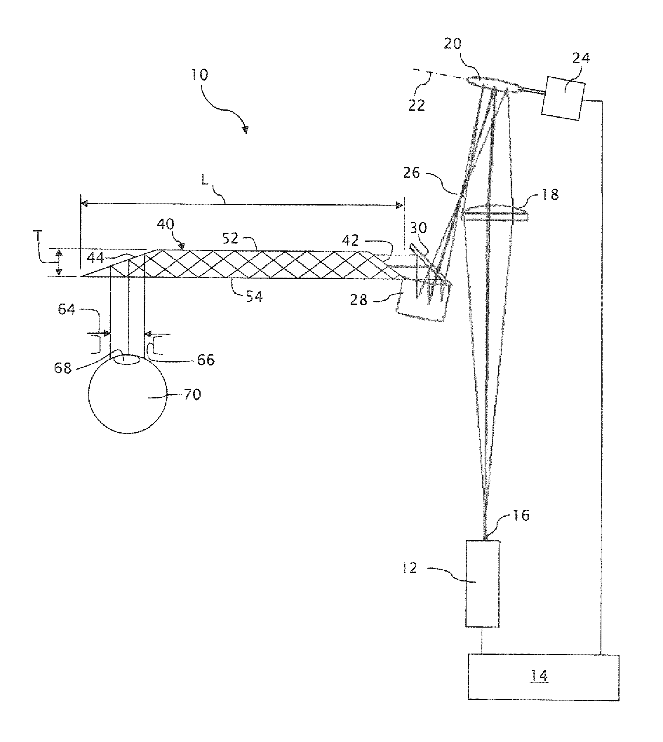
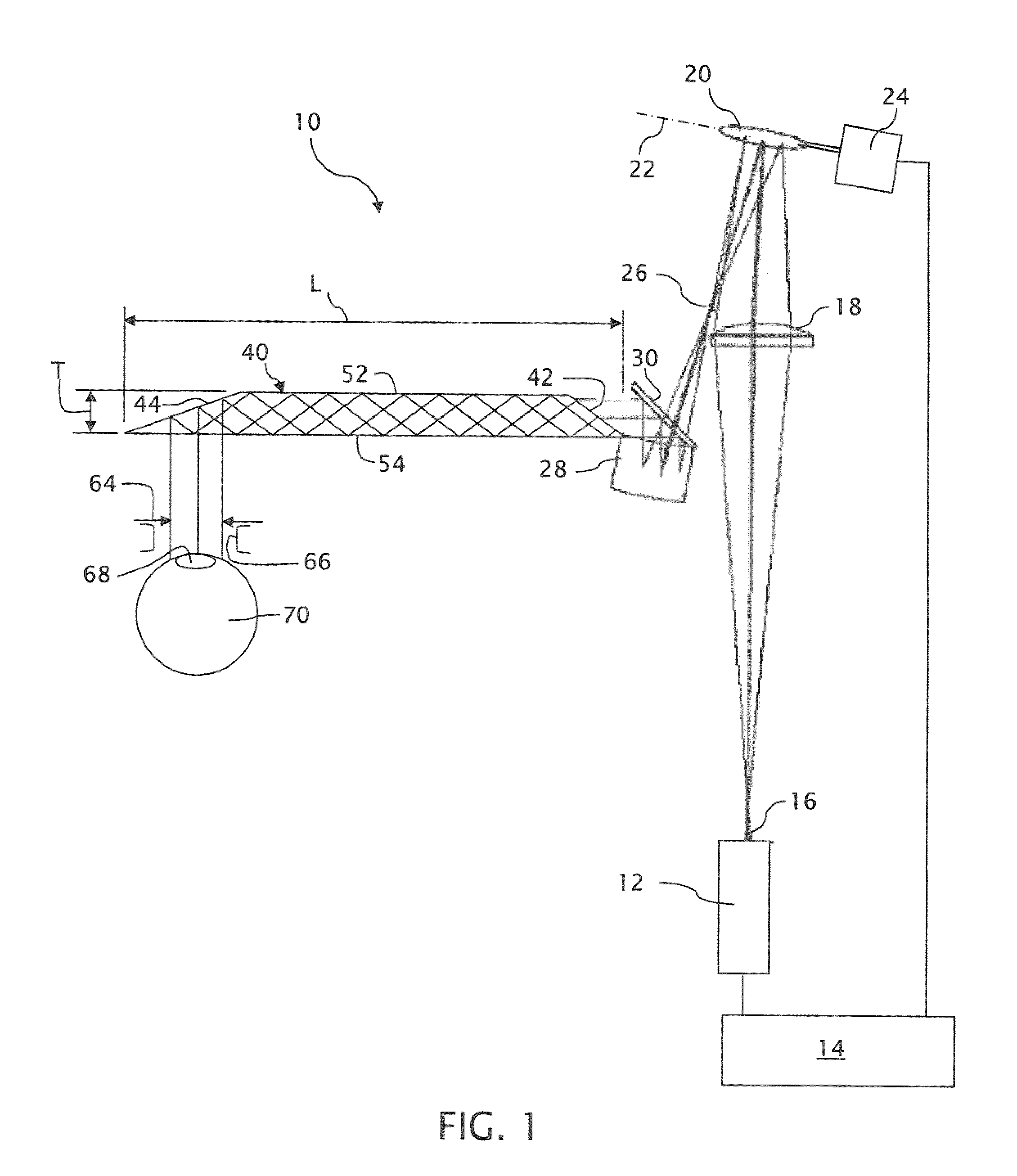
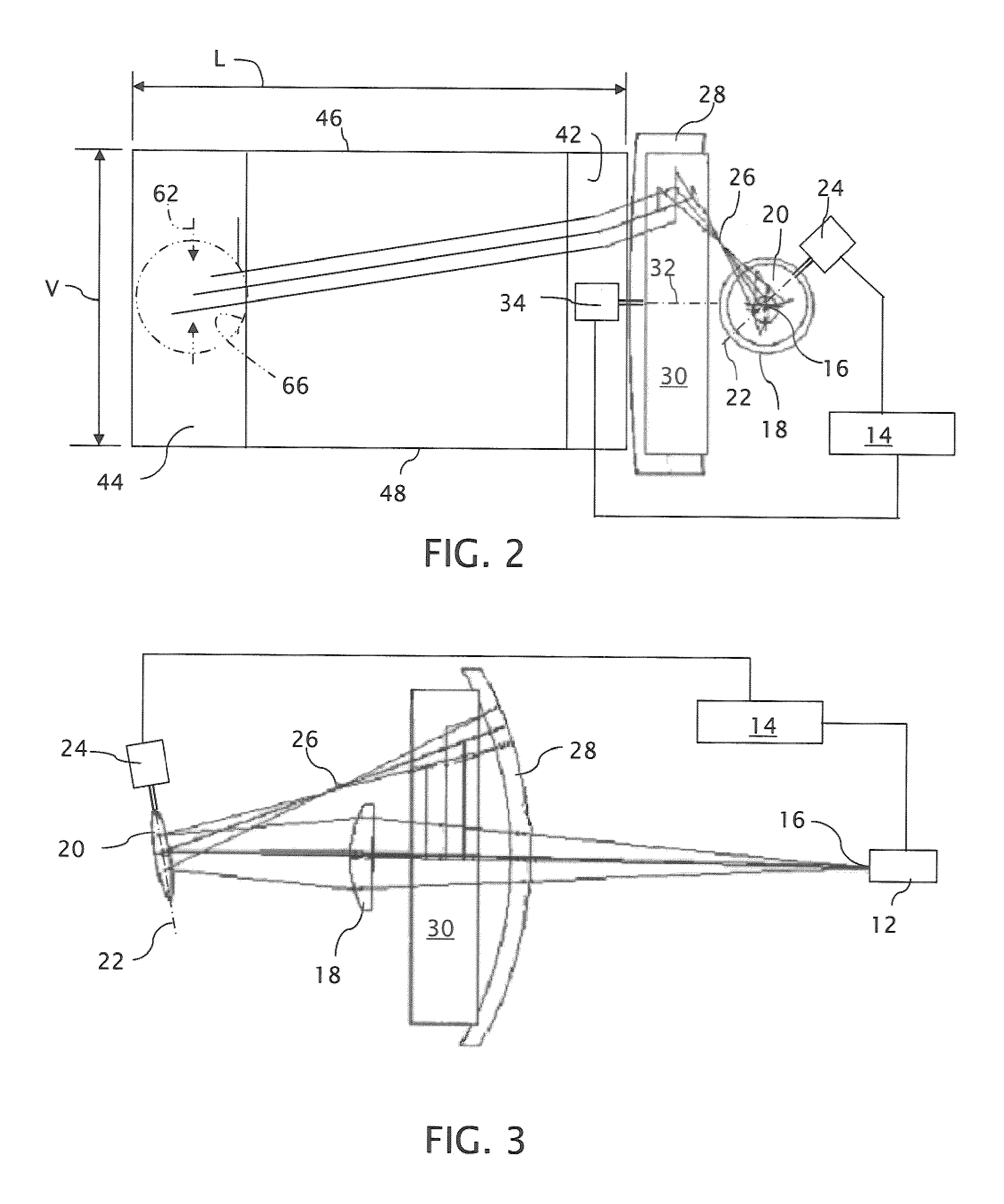
[0021]A compact near eye display system 10 in accordance with the invention is shown in FIGS. 1-3 in a form that generates virtual images using a two-dimensional scanning system. A light source 12, which is preferably modulatable in both intensity and color, receives a video signal from a controller 14 for generating raster images. For producing color raster images, the light source 12 can be formed by a conventional white light source in combination with color filters or by a combination of different monochromatic light sources such as different color light emitting diodes (LEDs). Monochromatic raster images can be produced by a monochromatic light source modulatable in intensity alone.

[0022]The light source 12 preferably forms a point source 16 for generating a single point within the intended virtual image. An imaging optic 18, preferably in the form of a refractive lens, relays an image of the point source 16 to a focal surface 26 of a focusing optic 28, which preferably takes t...


PUM


Abstract

A compact near eye display generates image segments for a first dimension of an intended image. Each of the image segments is transformed into angularly distinguished beamlets that converge through a first dimension pupil within an eyebox. A scanning optic angularly separates the angularly distinguished beamlets of different image segments for creating a second dimension pupil. The angularly distinguished and separated beamlets propagate along a waveguide in a form that minimizes the thickness of the display in front of a viewer's eye and limits the overall size of the optics required to support the projection of virtual images into the viewer's eye.

Description

TECHNICAL FIELD[0001]The invention relates to near eye displays for projecting virtual images into viewers' eyes including such displays that generate at least one dimension of the images by optical scanning and such displays that include waveguides for conveying image information to the viewers' eyes in a compact form.BACKGROUND OF THE INVENTION[0002]Scanning mirrors operated in synchronism with modulated light sources have been used for generating images that are projected onto viewing screens. Typically, the scanning mirrors are incrementally inclined in synchronism with the output of the modulated light sources for writing raster traced images onto the viewing screens in accordance with video signals. Two-dimensional scanning mirror systems (e.g., mirrors rotatable about two orthogonal axes) can be used in combination with synchronized light sources (usually lasers) for generating two-dimensional images. Alternatively, one-dimensional scanning mirror systems (e.g., mirrors rotat...

Claims


Application Information

Patent Timeline
Patent Type & Authority Patents(United States)
IPC IPC(8): G02B27/01
CPCG02B6/00G02B26/10G02B27/0101G02B2027/015
Inventor BURKE, ELLIOT
Owner VUZIX
Why Eureka
Try Eureka