Optical fiber alignment measurement method and apparatus

a technology of optical fiber and alignment measurement, applied in the field of systems, apparatus and methods for measuring the alignment of optical fibers in optical connectors, can solve the problems of limited accuracy, long test time, and relatively high equipment costs, and achieve the effect of high resolution

Active Publication Date: 2014-04-15
TE CONNECTIVITY NEDERLAND
View PDF21 Cites 10 Cited by
  • Summary
  • Abstract
  • Description
  • Claims
  • Application Information

AI Technical Summary

Problems solved by technology

Present system, apparatus, and methods for measuring the alignments of fibers in connectors have many disadvantages, such as, long test times, limited accuracy and relatively high equipment costs.
Such systems also are relatively expensive.
Furthermore, if it is desired to assure the quality of the cable and connector assembly, a separate, subsequent performance test, such as an insertion loss test, is still required.

Method used


Image

  • Optical fiber alignment measurement method and apparatus
  • Optical fiber alignment measurement method and apparatus
  • Optical fiber alignment measurement method and apparatus

Examples


Embodiment Construction

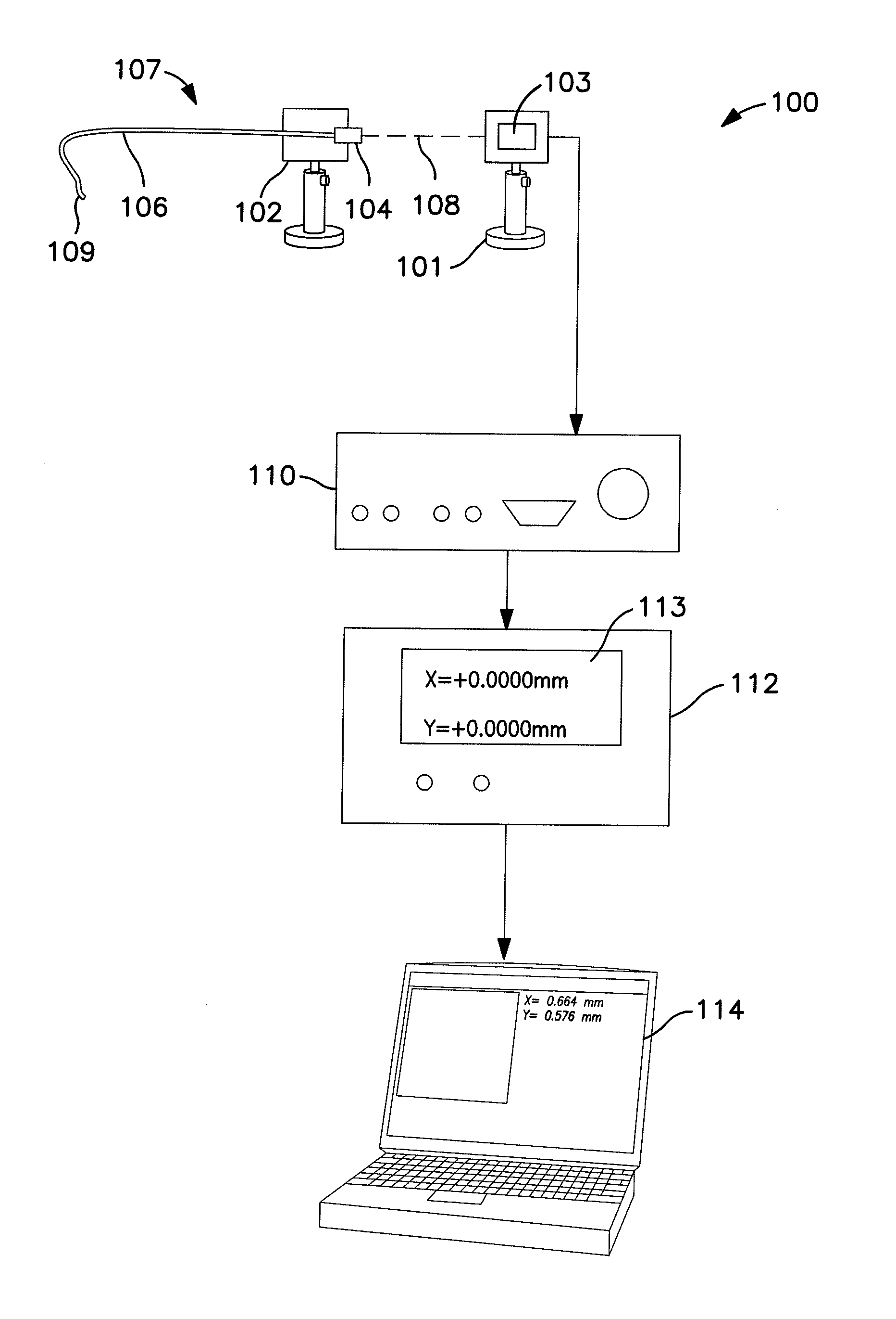
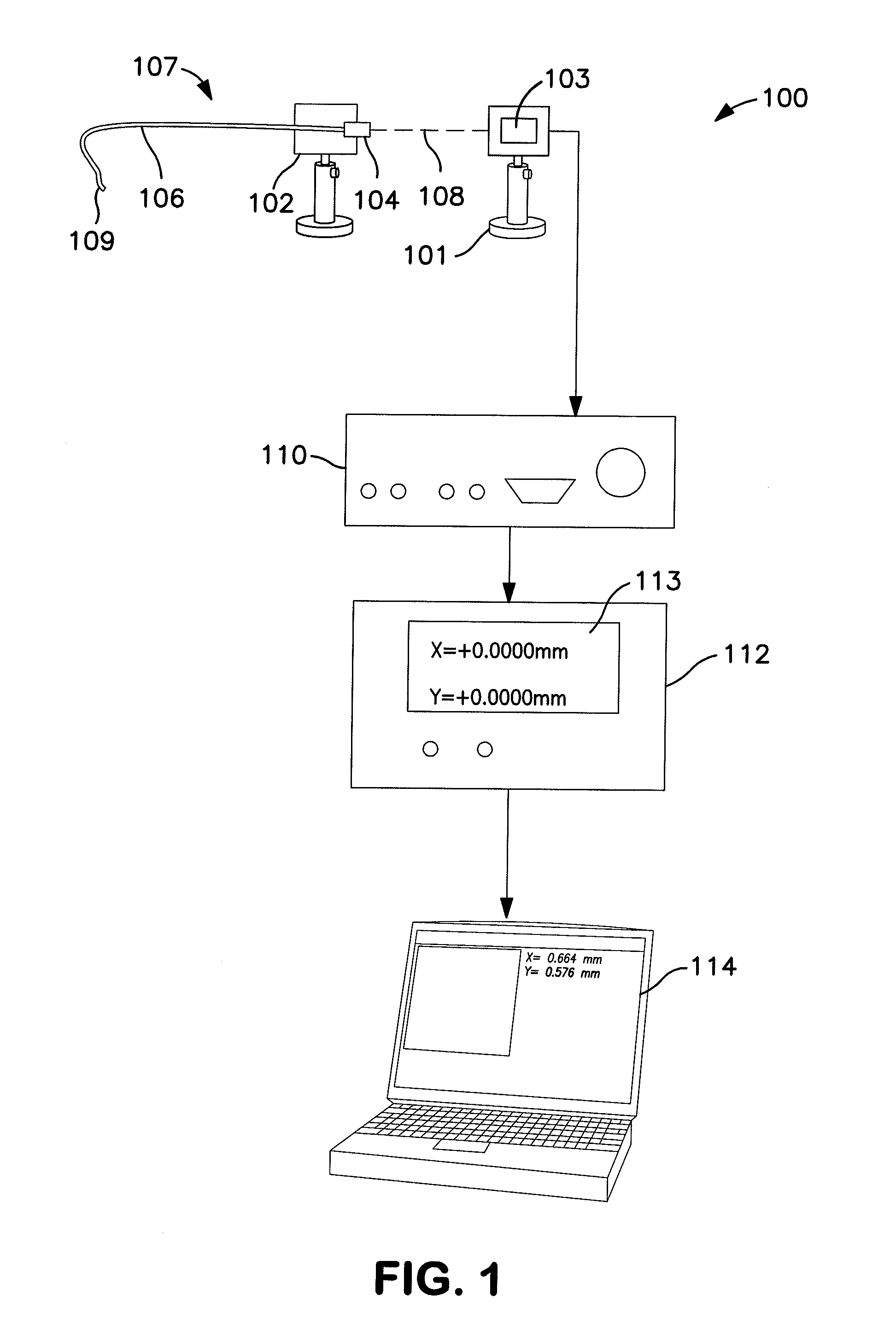
[0015]A position sensitive device, also sometimes called a position sensing detector, position sensitive detector, or position sensing device (hereinafter PSD) is an optical position sensor that measures the position of a light spot on a sensor surface in one or two dimensions. PSDs generally are one or two types that work according to different principles. In the first class, isotropic sensors, the sensors have an isotropic sensor surface that has a raster-like structure that supplies continuous position data. The principle of isotropic sensors is grounded on the basic operation of a PIN diode. Particularly, when a spot of light within the spectral range of silicon strikes the surface of a PIN diode, a photocurrent is generated that flows from the point of incidence of the light beam through the resistive layers of the PIN diode to electrodes embedded within the diode. Since the ion implanted layer of a PIN diode has very uniform resistivity, the current at each electrode is invers...


PUM

PropertyMeasurementUnit
distanceaaaaaaaaaa
current flowaaaaaaaaaa
speedaaaaaaaaaa

Abstract

A measurement system comprising an analog position sensitive device is provided that can measure the XY position of a plurality of light beams at very high resolution. In accordance with one exemplary associated method, a connector bearing one or more optical fibers is fixedly positioned before a position sensing detector so that light emanating from the ends of the optical fibers will strike the position sensing detector. A light beam is passed through at least one opening in the connector, such as a guide pin hole onto the detecting surface of the PSD to establish the position of the connector. Next, each optical fiber in the connector is individually illuminated sequentially so that the light emanating from the fiber falls on the position sensing detector. The locations of all of these light beams striking the PSD are compared to position of the light beam passed through the guide pins and / or to each other to determine if all the fibers are in the correct positions relative to the connector. In addition, it is possible to simultaneously measure the magnitude of the light emanating from each fiber in order to measure the quality of the light transmission through the connector / cable assembly.

Description

FIELD OF TECHNOLOGY[0001]The invention pertains to systems, apparatus, and methods for measuring the alignment of optical fibers in an optical connector, such as to assure that the ferrules in a connector and the optical fibers positioned within those ferrules are within expected tolerances.BACKGROUND OF THE INVENTION[0002]Optical fiber cables are becoming increasingly more common for use in transmitting high speed data in communication networks. These optical fibers must be terminated to equipment (e.g., optical transmitters such as lasers and LEDs or optical receivers, such as photodiodes, etc.) or other fibers. This is done through the use of ferrules and connectors at the ends of optical fiber cables that join with mating connectors on the termination equipment. As is well known, these connectors comprise ferrules within which the individual optical fibers are positioned very precisely so that they will align with the light receiving or light emitting face of the component to wh...

Claims


Application Information

Patent Timeline
Patent Type & Authority Patents(United States)
IPC IPC(8): G01B11/14G01N21/00G01B11/00
CPCG02B6/3885G01B11/27G02B6/3843
Inventor DUIS, JEROEN ANTONIUS MARIARIETVELD, JAN WILLEM
Owner TE CONNECTIVITY NEDERLAND
Why Eureka
Try Eureka