
Nano vacuum tube arrays for energy storage

a vacuum tube array and energy storage technology, applied in the direction of fixed capacitor details, multiple fixed capacitors, capacitors, etc., can solve the problems of limited charge/discharge rate of chemical batteries, limited reverse-biased diodes used for energy storage, and limited electrostatic storage in capacitors

Inactive Publication Date: 2014-04-15
THE BOARD OF TRUSTEES OF THE UNIV OF ILLINOIS
View PDF3 Cites 4 Cited by
  • Summary
  • Abstract
  • Description
  • Claims
  • Application Information

AI Technical Summary

Benefits of technology

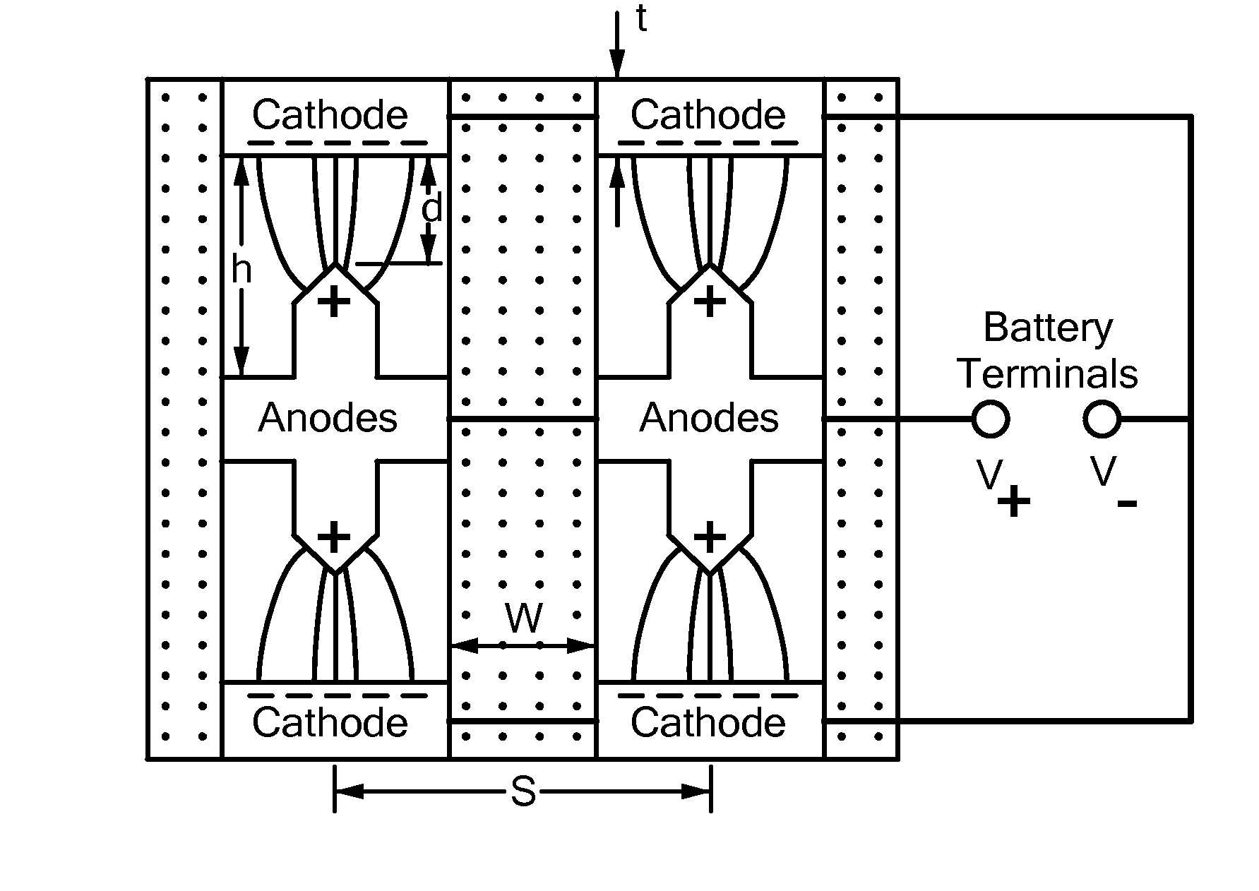
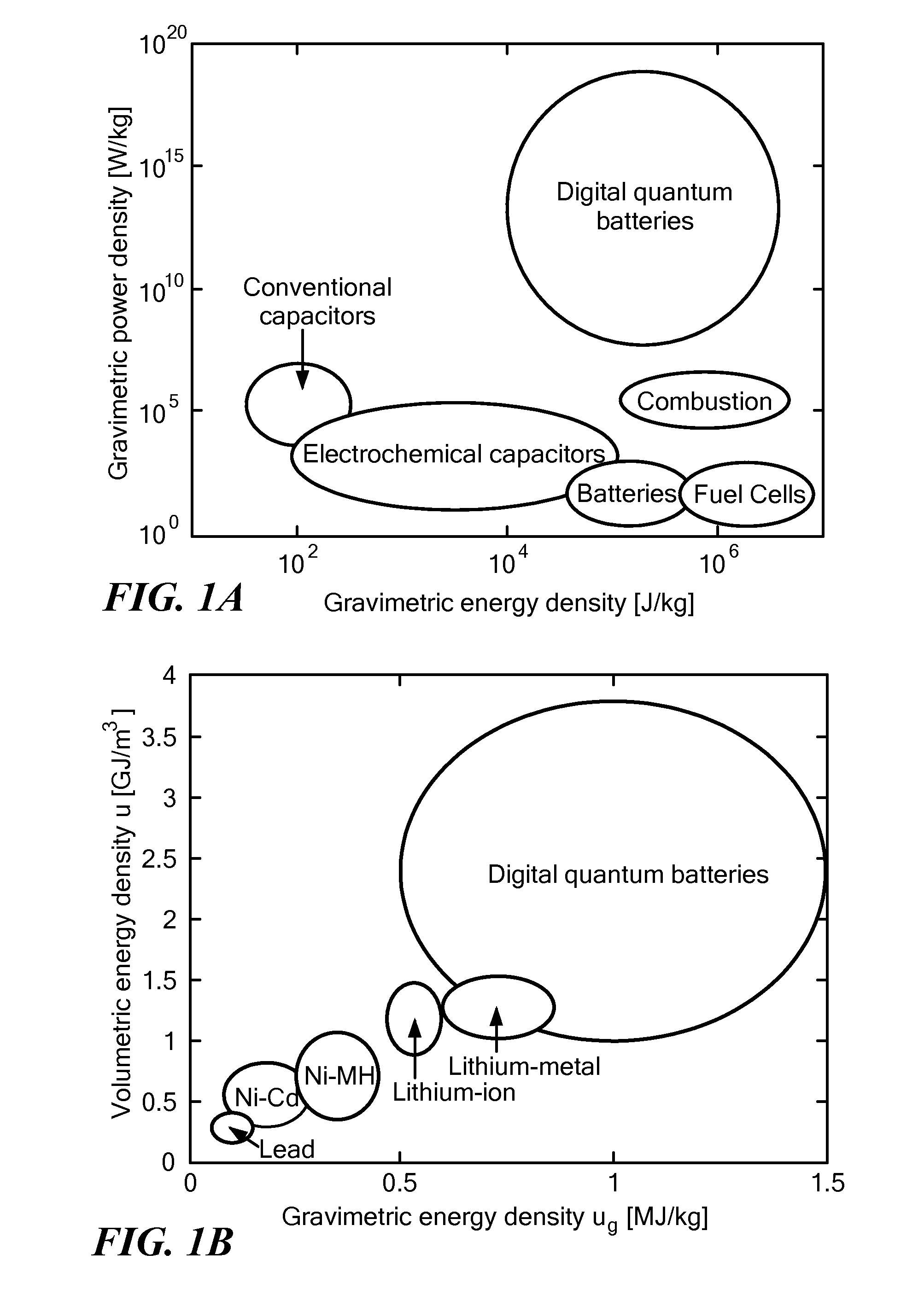
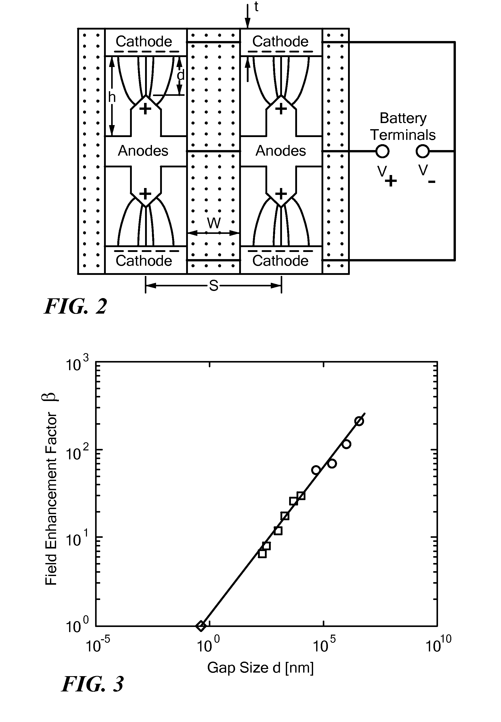
The patent describes a method for storing energy using vacuum tubes with sub-micrometer dimensions. These tubes have a region between the anodic and cathodic electrodes that is evacuated to a pressure below 10−6 Torr. The method involves storing an excess of electrons on the cathodic electrode. The patent also describes a device that can deliver powers in excess of 1010 W / kg, which is made up of an array of nano vacuum tubes with walls. The walls of these tubes have a region between the nano tip anodic electrode and the flat electrode that is evacuated to a pressure below 10−6 Torr. Overall, the invention provides a way to store and deliver energy using small vacuum tubes with sub-micrometer dimensions.

Problems solved by technology

Electrostatic storage in capacitors is limited by dielectric breakdown, while chemical batteries suffer from the drawback of limited charge / discharge rates.
Reverse-biased diodes used for energy storage are limited by field emission, avalanche breakdown, and Zener breakdown.
Conventional parallel plate capacitors can be charged and discharged quickly and they have a virtually unlimited life time, but their energy density is small, because of dielectric breakdown.
However, field emission, avalanche breakdown and Zener breakdown limit the electric field to about E=0.02 V / mm (in silicon with donor concentration N=1014 cm−3), and the energy density is less than in conventional capacitors.
Energy storage in semiconductor junctions is further limited by the fact that the depletion zone is not a perfect insulator and reverse saturation currents discharge the diode.

Method used


Image

  • Nano vacuum tube arrays for energy storage
  • Nano vacuum tube arrays for energy storage
  • Nano vacuum tube arrays for energy storage

Examples


Embodiment Construction

[0008]As used herein and in any appended claims, the term “nano vacuum tube” will refer to a vacuum tube characterized by sub-micrometer lengths in at least two dimensions.

[0009]Similarly, the term “nano-tip” refers to a conducting structure characterized by sub-micrometer lengths in at least two dimensions. A nano-tip may be pointed, curved, or flat.

[0010]In accordance with embodiments of the present invention, a method is provided for storing energy. The method has steps of:

[0011]a. providing an array of vacuum tubes having walls, each vacuum tube including[0012](1) an anodic electrode; and[0013](2) a cathodic electrode spaced apart from the anodic electrode; and[0014](3) a region intervening between the anodic electrode and the cathodic electrode of each vacuum tube evacuated to a pressure below 10−6 Torr; and

[0015]b. storing an excess of electrons on the cathodic electrode.

[0016]In accordance with alternate embodiments of the invention, the array of vacuum tubes may be character...


PUM

PropertyMeasurementUnit
pressureaaaaaaaaaa
electric fieldaaaaaaaaaa
gap sizesaaaaaaaaaa

Abstract

Methods and apparatus for storing information or energy. An array of nano vacuum tubes is evacuated to a pressure below 10−6 Torr, where each nano vacuum tube has an anodic electrode, a cathodic electrode spaced apart from the anodic electrode, and an intervening evacuated region. An excess of electrons is stored on the cathodic electrode.

Description

[0001]The present Application claims priority from U.S. Provisional Patent Application Ser. No. 61 / 253,605, filed Oct. 21, 2009, and incorporated herein by reference.[0002]This invention was made with government support under Grant DMS 03-25939 ITR, awarded by the National Science Foundation. The Government has certain rights in the invention.TECHNICAL FIELD[0003]The present invention relates to devices and methods for high-density storage of energy in materials configured as nano vacuum tubes subject to specified material and geometrical properties.BACKGROUND ART[0004]The position of an electrical charge within an electric field represents a potential energy that may be converted to work through displacement of the charge. Stable separation of electrical charge gives rise to storage of energy as potential energy, and is typically accomplished chemically, in batteries, or electrostatically, in capacitors. Electrostatic storage in capacitors is limited by dielectric breakdown, while ...

Claims


Application Information

Patent Timeline
Patent Type & Authority Patents(United States)
IPC IPC(8): H01G4/38H01G4/02
CPCH01G4/02H01G4/38
Inventor HUBLER, ALFRED W.OSUAGWU, ONYEAMA
Owner THE BOARD OF TRUSTEES OF THE UNIV OF ILLINOIS
Learn More