Power converter

a power converter and converter technology, applied in the direction of dc source parallel operation, efficient power electronics conversion, electric variable regulation, etc., can solve the cost/efficiency tradeoff in the most applications of power converter design, the power supply for these types of equipment is relatively expensive to construct, and the implementation cost is relatively high, so as to simplify the control circuitry. , the effect of reducing the cost of the control circuitry and facilitating the conversion

Active Publication Date: 2014-04-15
COMMERGY TECH
View PDF29 Cites 2 Cited by
  • Summary
  • Abstract
  • Description
  • Claims
  • Application Information

AI Technical Summary

Benefits of technology

[0005]It is an object therefore of the present invention to provide a power converter that is relatively inexpensive to construct while at the same time being highly efficient in use. It is a further object of the present invention to provide a power converter that is relatively simple to construct and manufacture.STATEMENTS OF INVENTION
[0046]In a further embodiment of the invention there is provided a power converter in which the means to sense the intermediate voltage fed to the output is provided by way of a differential sensing function between the input rail and the output voltage of the pre-regulator stage. In one embodiment, the differential sensing function comprises a PNP transistor. This is a simple configuration of means to sense the intermediate voltage fed to the output.

Problems solved by technology

Usually, there is a cost / efficiency tradeoff in most applications of power converter design.
Heretofore, this has often resulted in the power supply for these types of equipment being relatively expensive to construct.
There are however problems with such an approach as it tends to be relatively expensive to implement while still not being highly efficient i.e. in the range of 90%+ efficiency.

Method used


Image

  • Power converter
  • Power converter
  • Power converter

Examples


Embodiment Construction

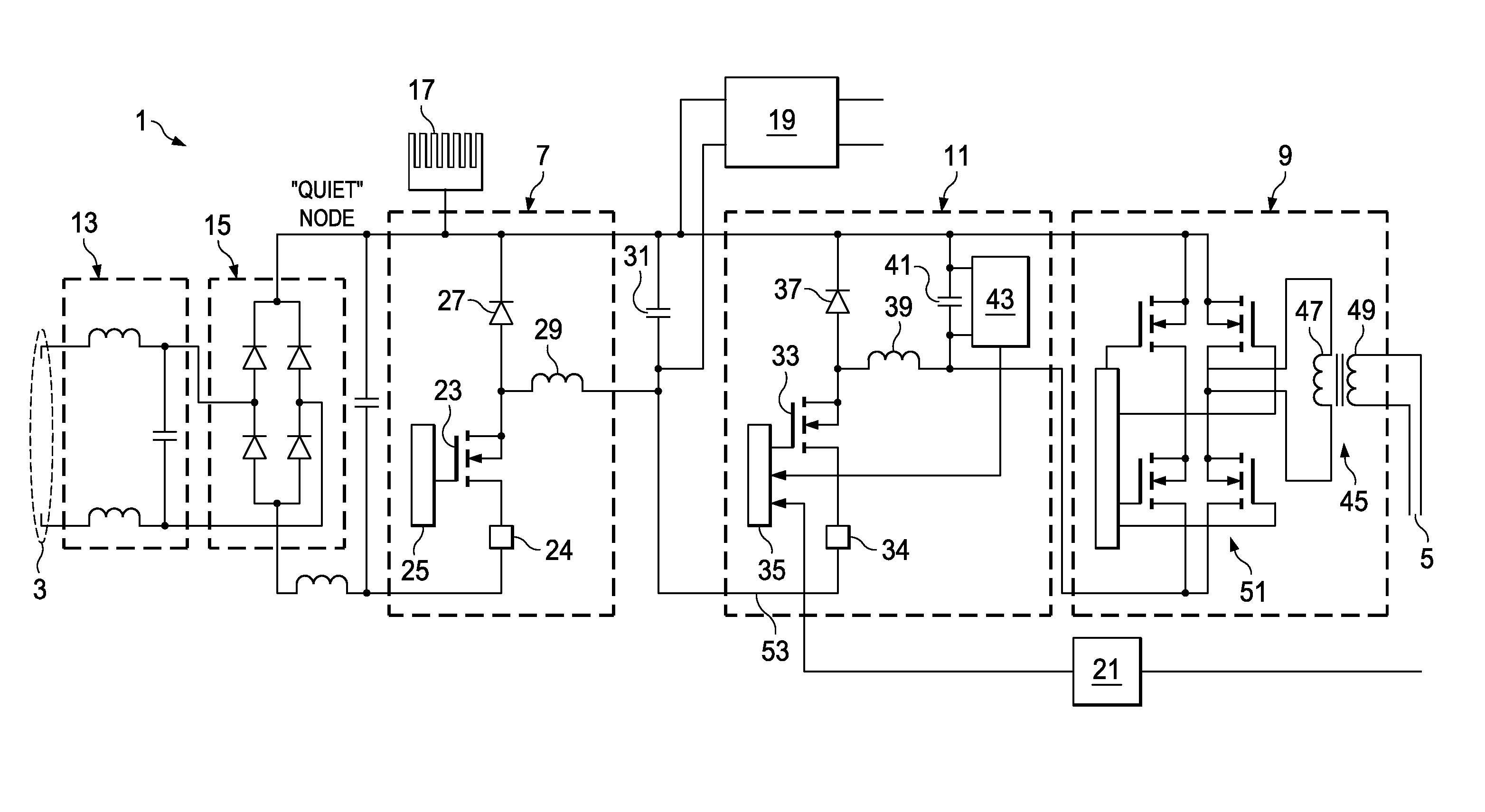
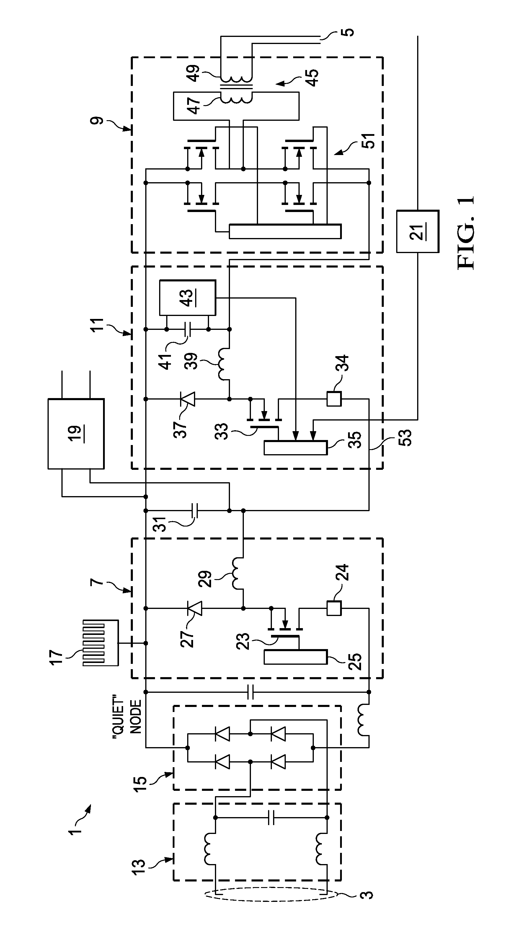
[0060]Referring to the drawings and initially to FIG. 1 thereof there is shown a power converter, indicated generally by the reference numeral 1, comprising a converter input 3, a converter output 5, a power factor correction (PFC) stage 7 provided by way of buck PFC stage, an isolation stage 9 and an intermediate buck pre-regulation stage 11 which follows the buck PFC stage 1. The power converter 1 further comprises an input filtering circuit 13 and an input rectification stage provided by way of a full bridge rectifier 15. The power converter further comprises a heat sink 17, a stand-by circuit 19 and an output sensing unit 21.

[0061]The buck PFC stage 7 further comprises a buck switch 23, a buck switch controller 25, a buck diode 27 and a buck inductor 29 which feed a bulk capacitor 31. The intermediate buck pre-regulation stage 11 further comprises a buck switch 33, a buck drive 35, a buck diode 37 and a buck inductor 39 which in turn feed an intermediate bulk capacitor 41. A dif...


PUM


Abstract

This invention relates to a power converter (1) comprising a converter input (3), a converter output (5), a power factor correction (PFC) stage (7) and an isolation stage (9). The PFC stage (7) is implemented by way of a buck PFC with low side drive and low side current sensing, There is provided a third stage, an intermediate buck pre-regulation stage (11), intermediate the buck PFC stage (7) and the isolation stage (9), Control of the power converter output voltage is achieved by varying the duty cycle of the intermediate buck pre-regulation stage (11) and therefore the isolation stage (9) may be an unregulated stage operated as a fixed DCDC voltage converter. The isolation stage (9) is operated as a 50%-50% duly cycle double ended stage. The configuration of power converter allows for a relatively inexpensive, highly efficient converter with 90%+ efficiency and simplified control.

Description

RELATED APPLICATIONS[0001]The subject application is a U.S. National Stage application that claims the priority of International Application No. PCT / EP2006 / 067245, filed on 10 Oct. 2006, which claims the priority of Irish National Application Nos.: S2005 / 0683, filed on 10 Oct. 2005 and 2006 / 0190, filed on 10 Mar. 2006.[0002]This invention relates to a power converter. More particularly, this invention relates to an AC / DC converter.[0003]Power converters and in particular AC / DC power converters are used in a wide range of applications. Generally speaking, these power converters are used to transform the incoming AC mains supply line voltage to one or more DC voltages suitable for use with the equipment that the power converter is charged with supplying voltage to. In many cases, the power converter will transform the AC mains line voltage into several DC line voltages such as in the case of electronic equipment. When designing a power converter, there are essentially two main conside...

Claims


Application Information

Patent Timeline
Patent Type & Authority Patents(United States)
IPC IPC(8): H02J1/10G05F1/00
CPCH02M1/42Y02B70/12Y02B70/10
Inventor YOUNG, GEORGETOMLINS, GARRYBARRY, MICHAEL JOHNBARNARD, JACOBUS MARTHINUS
Owner COMMERGY TECH
Why Eureka
Try Eureka