
X-ray examination apparatus and method

a technology of x-ray and x-ray, applied in the field of x-ray examination apparatus, can solve the problems of high hardware cost, difficult realization of kv transients, and high hardware effort for photon-counting spectral ct,

Active Publication Date: 2014-04-15
KONINK PHILIPS ELECTRONICS NV
View PDF17 Cites 19 Cited by
  • Summary
  • Abstract
  • Description
  • Claims
  • Application Information

AI Technical Summary

Benefits of technology

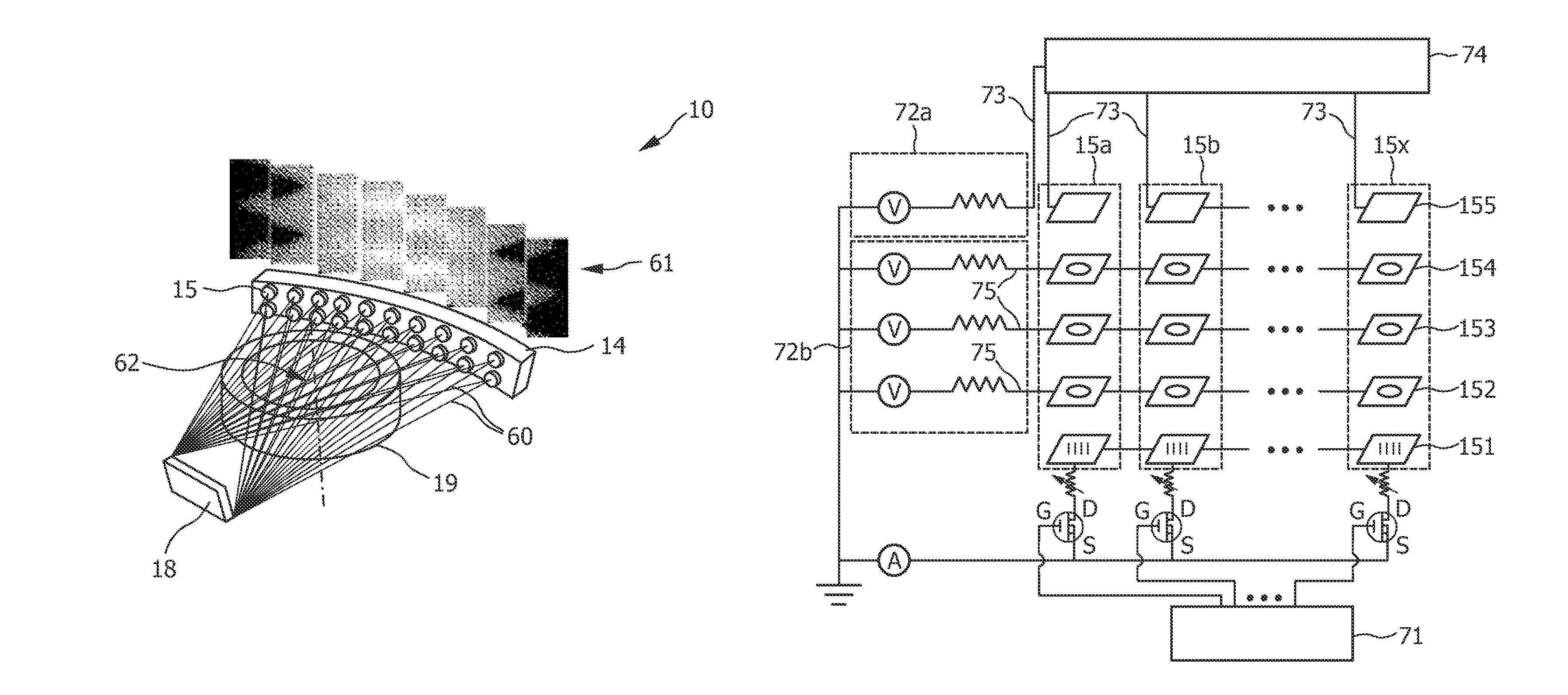
[0018]The present invention is based on the idea to use an inverse CT system arrangement in which preferably only one X-ray source or a group of (but not all) X-ray sources is active at a given time, particularly for spectral CT applications. To switch a particular X-ray source, or said group of X-ray sources, over to achieve that it emits X-rays at a different energy spectrum than before, as is required for spectral CT applications, takes some time. This time of switching over a particular X-ray source, or said group of X-ray sources, is exploited according to the present invention to switch this particular X-ray source, or said group of X-ray sources, off (so that it does not emit any X-ray radiation) and to switch on one or more X-ray sources or groups of X-ray source—subsequently and preferably only one or one group at a time—to emit X-ray radiation in the meantime. Thus, during this time detection signals are also obtained which saves much time. Hence, according to the present invention the inverse-CT source modulation pattern is extended by an advantageous alternating kV modulation scheme.
[0031]In an embodiment said control unit is adapted for controlling said X-ray sources to emit X-rays in groups such that a first group of X-ray sources are emitting X-rays with overlapping energy spectra and that thereafter other groups of X-ray sources are separately and subsequently emitting X-rays at, in particular the same, energy spectrum. This embodiment provides the advantage that with an energy-resolving detector the source can be identified leading to a fast acquisition time and high accuracy.

Problems solved by technology

Dual-source CT systems with dissimilar kVp (peak kilovoltage) settings: only two material components can be unambiguously separated; high hardware costs, since two sources and two detectors have to be mounted.
Fast dual kVp switching: only two material components can be unambiguously separated; low spectral separation, since strong kV transients are difficult to realize.
Photon-counting spectral CT: detection requires high hardware effort.

Method used


Image

  • X-ray examination apparatus and method
  • X-ray examination apparatus and method
  • X-ray examination apparatus and method

Examples


Embodiment Construction

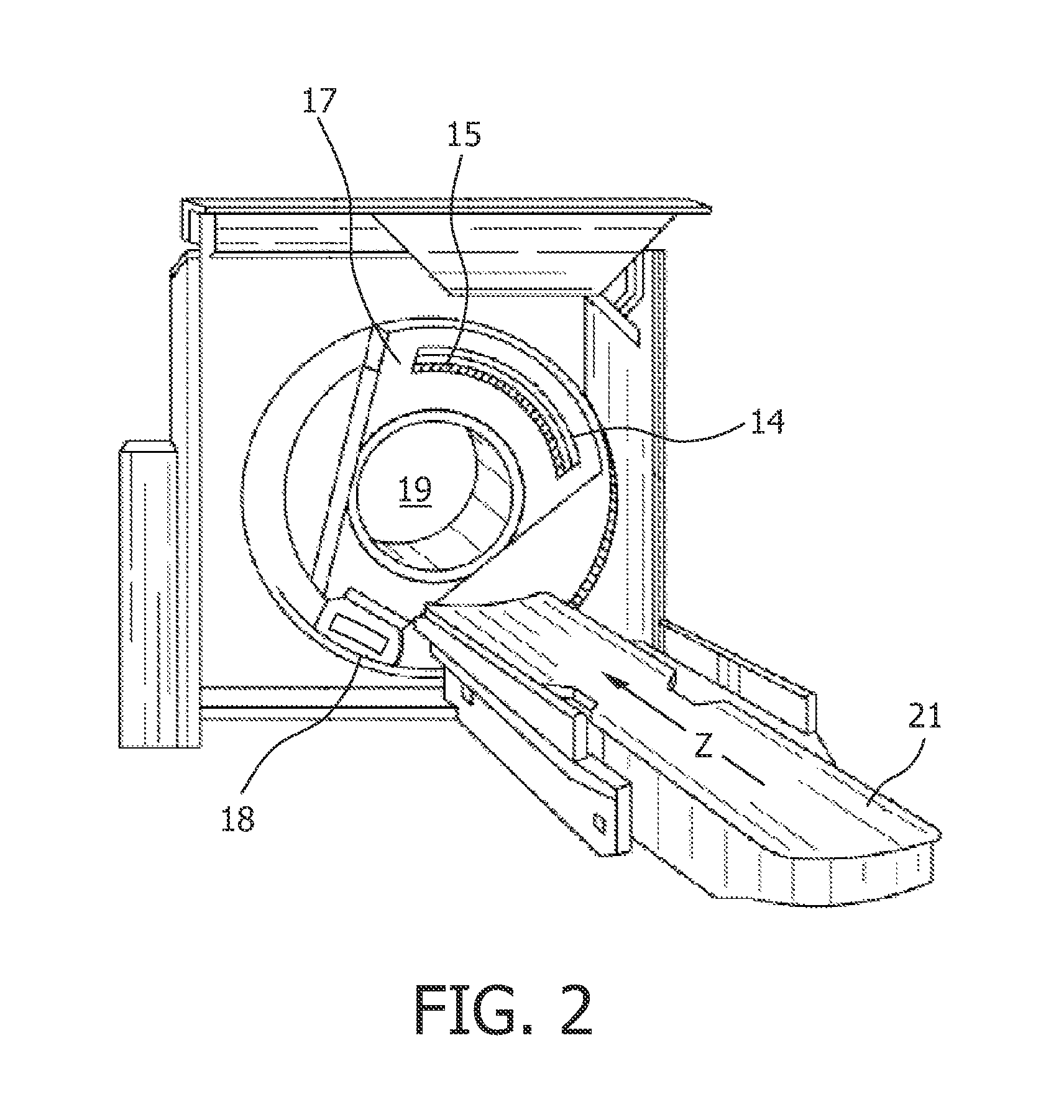
[0042]The present technique is generally directed towards an imaging technique, such as a tomosynthesis imaging technique, to generate useful images for medical and non-medical applications. As will be appreciated by those of ordinary skill in the art, the present techniques may be applied in various medical and non-medical applications, such as passenger and / or baggage screening, to provide useful three-dimensional data and context. To facilitate explanation of the present techniques, however, a medical implementation will be generally discussed herein, though it is to be understood that non-medical implementations are also within the scope of the present techniques.

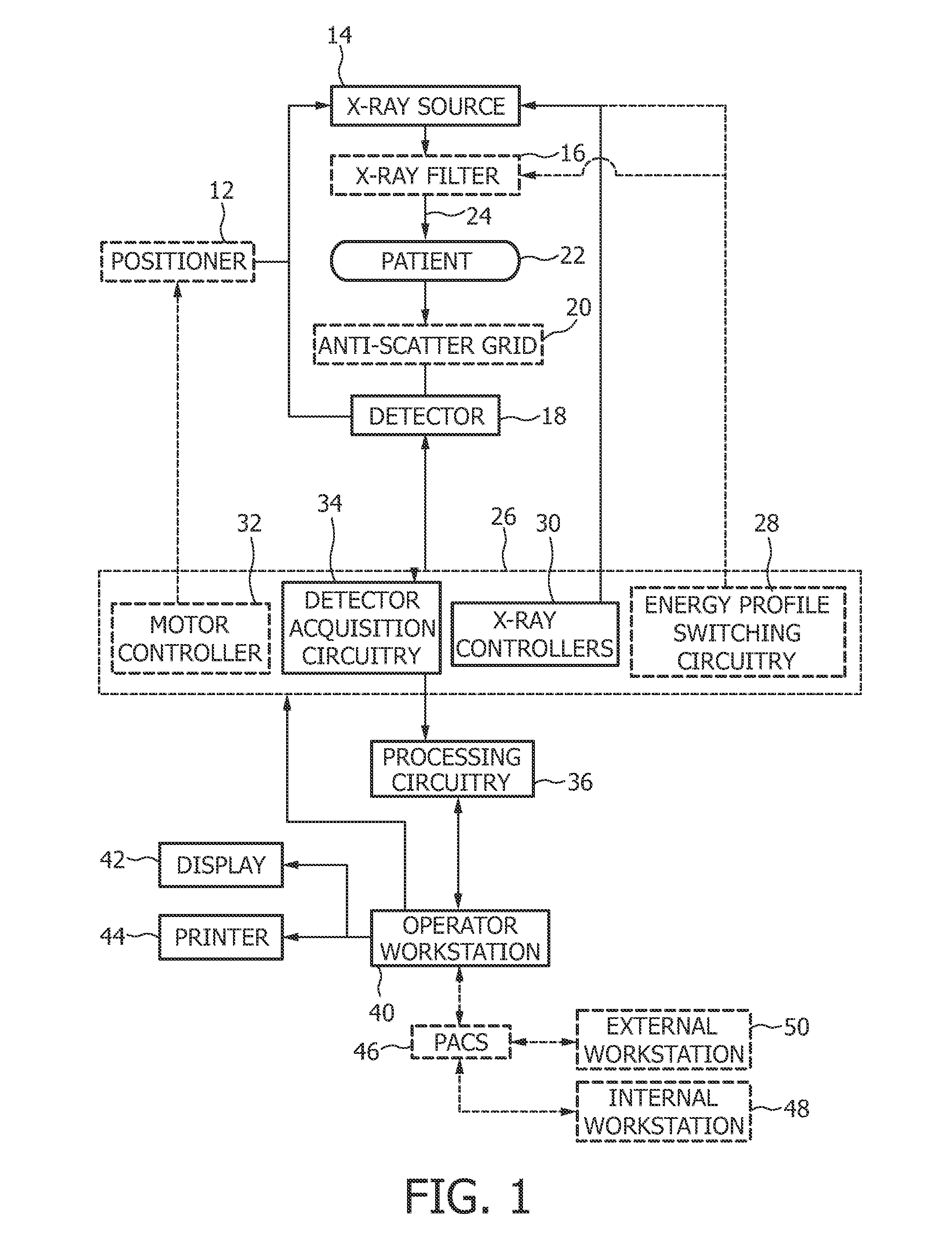
[0043]FIG. 1 shows a schematic view of an exemplary embodiment of a multi-energy examination apparatus 10 in accordance with the present invention. The apparatus 10 includes a positioner or a support 12 that supports an X-ray source unit 14. The support 12 may include one or more X-ray filters 16 which may be positioned...


PUM


Abstract

The present invention relates to an examination apparatus and a corresponding method to realize a Spectral x-ray imaging device through inverse-geometry CT. The proposed examination apparatus comprises: an X-ray source unit (14) comprising a plurality of X-ray sources (15) for emitting X-rays (24) at a plurality of locations, an X-ray detection unit (18) for detecting X-rays emitted from one or more of said X-ray sources (15) after penetration of an examination area (19) between said X-ray source unit (14) said X-ray detection unit (18) and for generating detection signals, a processing unit (36) for processing the generated detection signals, and—a control unit (26) for controlling said X-ray sources (15) to subsequently, alone or in groups emit X-rays at least two different energy spectra such that in the time interval, during which a particular X-ray source (15a) or said group of X-ray sources (15a,15d, 15g), is switched over to emit X-rays at a different energy spectrum, said particular X-ray source (15a) or said group of X-ray sources (15a, 15d, 15g) is switched off and one or more other X-ray sources (15b, 15c) or groups of X-ray sources (15b, 15e, 15h; 15c, 15f, 15i) are subsequently switched on to emit X-rays.

Description

FIELD OF THE INVENTION[0001]The present invention relates to an X-ray examination apparatus and a corresponding method as well as a computer program for control of said apparatus.BACKGROUND OF THE INVENTION[0002]Color (or spectral) X-ray imaging has been identified as most promising route for future development of CT (Computer Tomography) by all vendors of medical CT scanners. However, CT vendors obviously follow different approaches to enter the spectral domain. This is mainly given due to the fact that hardware realization of a spectral CT scanner is a non-trivial task.[0003]In a novel ‘inverse’ geometry CT (IGCT) system design, as described, for instance, in DeMan, B. et al., “Inverse geometry CT: The next-generation CT architecture?”, IEEE Nuclear Science Symposium Conference Record, 2007, M07-2, p. 2715-2716, a large distributed X-ray source with an array of discrete electron emitters and focal spots, and a high frame-rate flat-panel X-ray detector is used. With the advent of c...

Claims


Application Information

Patent Timeline
Patent Type & Authority Patents(United States)
IPC IPC(8): H05G1/56H05G1/02H05G1/32H05G1/70H01J35/06H05G1/10
CPCA61B6/4028A61B6/032A61B6/4007A61B6/4241A61B6/4035A61B6/405A61B6/482
Inventor BAEUMER, CHRISTIANVOGTMEIER, GEREON
Owner KONINK PHILIPS ELECTRONICS NV
Learn More