Method and system for a turbocharged engine

a turbocharged engine and turbo technology, applied in the direction of machines/engines, output power, electric control, etc., can solve the problems of reducing overall egr efficiency, difficult to achieve high pressure egr (hp-egr), and delays in controlling both lp-egr and hp-egr, so as to reduce exhaust emissions and improve fuel economy

Inactive Publication Date: 2014-04-22
FORD GLOBAL TECH LLC
View PDF45 Cites 70 Cited by
  • Summary
  • Abstract
  • Description
  • Claims
  • Application Information

AI Technical Summary

Benefits of technology

[0003]In an effort to meet stringent federal government emissions standards, engine systems may be configured with exhaust gas recirculation (EGR) systems wherein at least a portion of the exhaust gas is recirculated to the engine intake. Such EGR systems enable reduction in exhaust emissions while also improving fuel economy, especially at higher levels of engine boost.
[0008]A timing of opening the first and second intake valves may be coordinated with a timing of opening of first and second exhaust valves coupled to the first and second exhaust passages, respectively. For example, higher pressure exhaust gases may be flowed through the turbine before release to the atmosphere or recirculated at higher pressure, while lower pressure exhaust gases may be directed to the atmosphere without flowing through the turbine or recirculated at or below barometric pressure. In addition to separating the HP-EGR from the LP-EGR, the staggered exhaust valve timings of the distinct exhaust valves increases the heat recovered from the exhaust gases. Also, by delivering the HP-EGR downstream of the compressor while delivering the LP-EGR through an intake passage not including the compressor, EGR may be advantageously kept out of the compressor, reducing compressor fouling and contamination issues. By operating LP-EGR separate from HP-EGR, they can also be independently controlled, reducing EGR control delays during transients. As such, EGR benefits can be availed with engine boost over a larger range of engine speed / load conditions.

Problems solved by technology

However, Applicants have recognized that such EGR systems may have potential issues that can reduce overall EGR efficiency.
As one example, it may be difficult to achieve high pressure EGR (HP-EGR), even if a turbine was added.
Further still, since LP-EGR and HP-EGR require different control approaches, there may be delays in controlling both LP-EGR and HP-EGR, in particular, during transients.

Method used


Image

  • Method and system for a turbocharged engine
  • Method and system for a turbocharged engine
  • Method and system for a turbocharged engine

Examples


Embodiment Construction

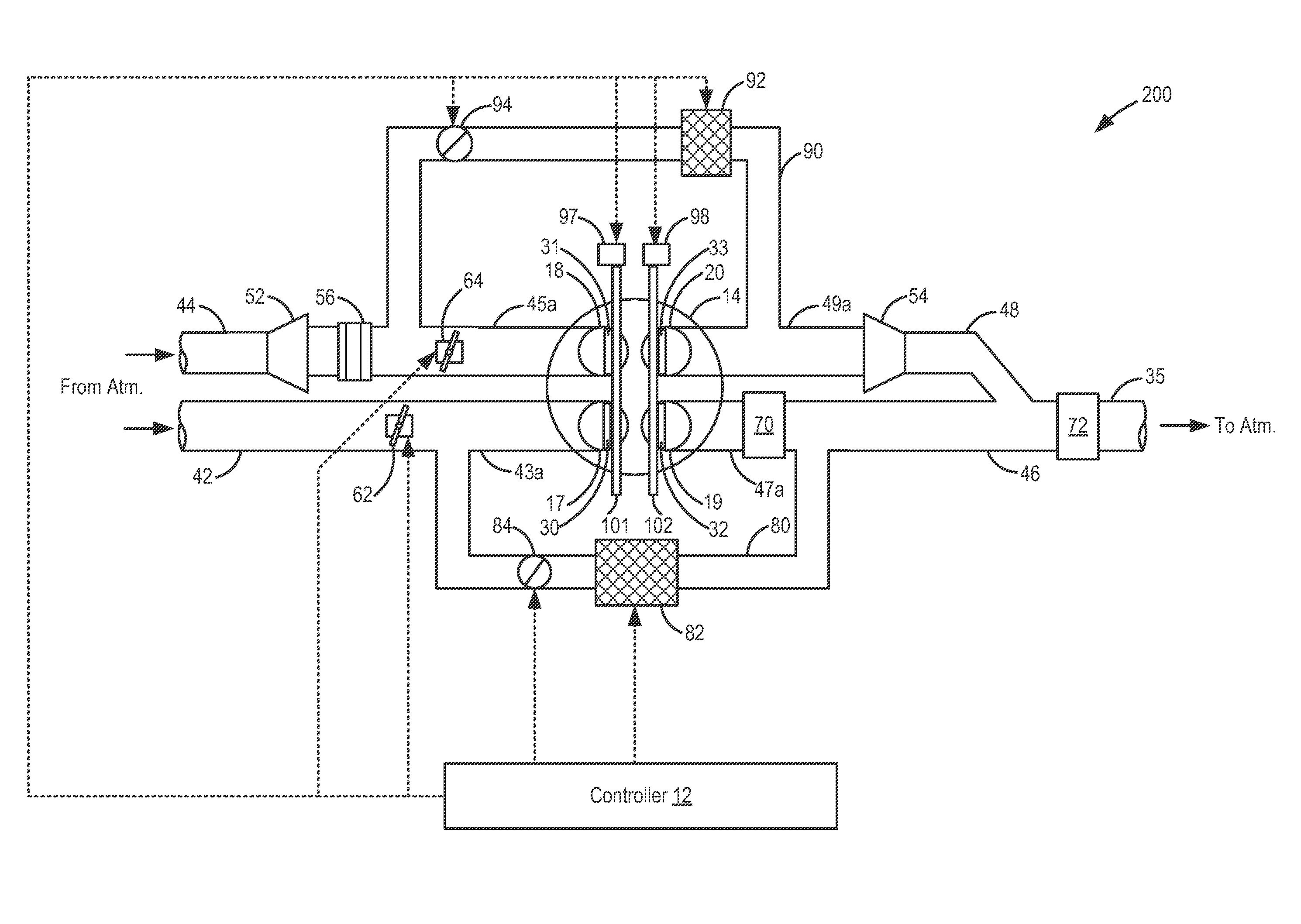
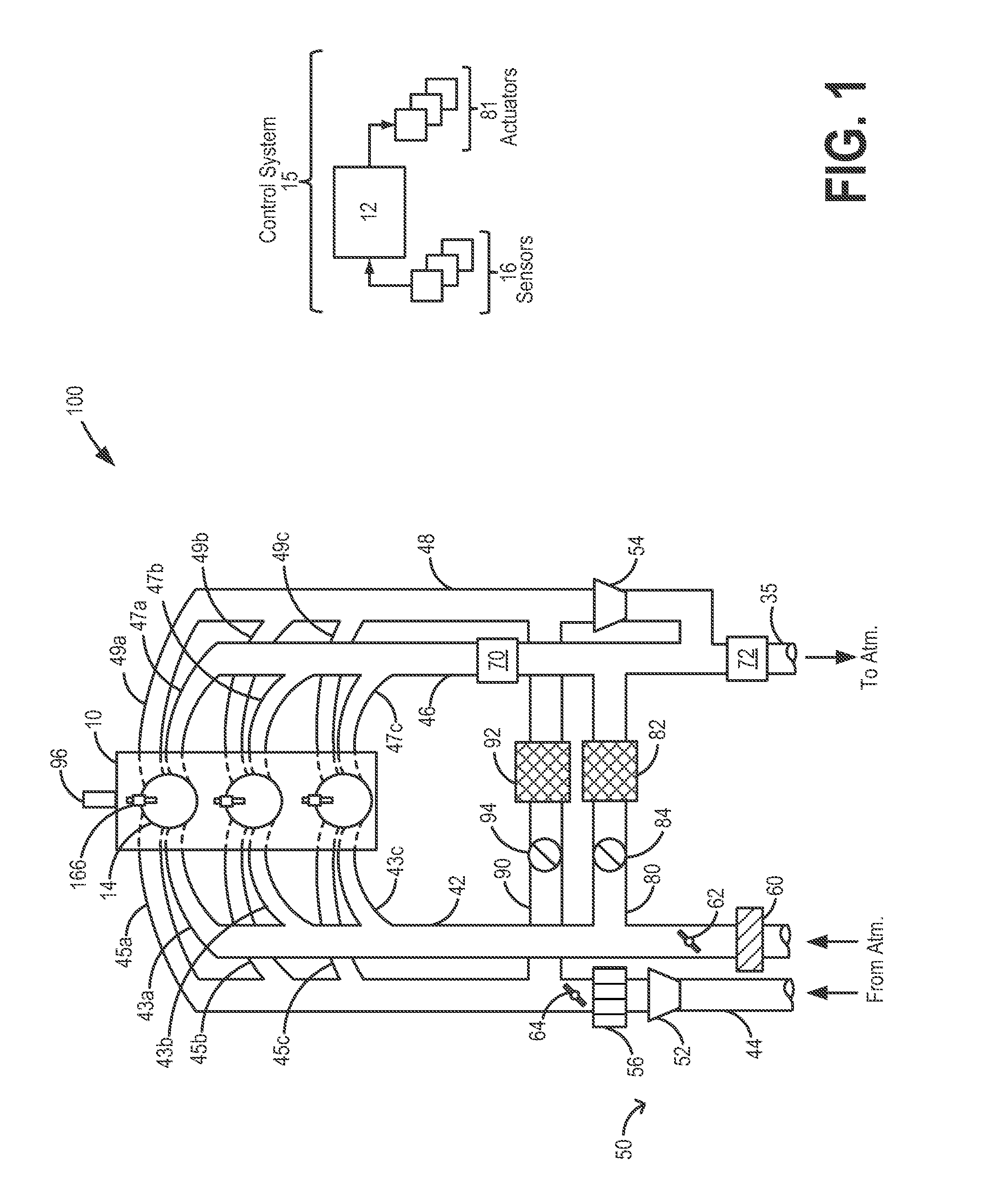
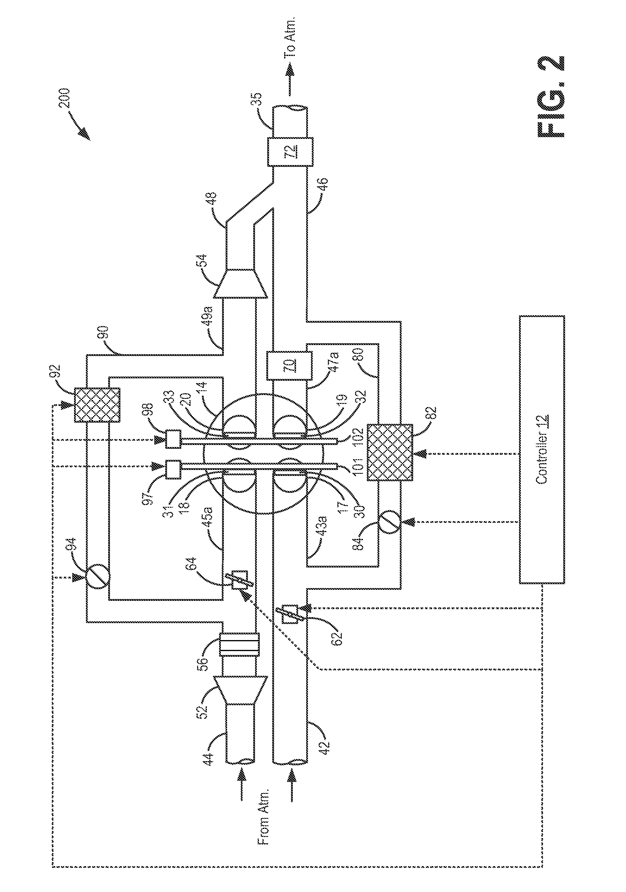
[0019]The following description relates to systems and methods for controlling an engine, such as the engine system of FIGS. 1-3, by providing aircharge of differing pressure and / or differing composition (e.g., different fresh air to EGR ratios) to an engine cylinder through distinct intake passages at different times in an engine cycle. Specifically, an intake aircharge at or below barometric pressure can be provided to the cylinder separate from an intake aircharge at compressor pressure. Likewise, an intake aircharge including recirculated exhaust gas can be provided to the cylinder separate from an intake aircharge having fresh air. Still other combinations may be possible, as elaborated in FIG. 6. An engine controller may be configured to perform a control routine, such as the routine of FIG. 4, to open a first cylinder intake valve at an earlier timing than a second cylinder intake valve (FIG. 5), thereby providing a first aircharge of a first composition at a different time i...


PUM


Abstract

Methods and systems are provided for a boosted engine having a split intake system coupled to a split exhaust system. Aircharges of differing composition, pressure, and temperature may be delivered to the engine through the split intake system at different points of an engine cycle. In this way, boost and EGR benefits may be extended.

Description

CROSS REFERENCE TO RELATED APPLICATIONS[0001]The present application is a continuation-in-part of U.S. patent application Ser. No. 12 / 878,838, entitled “Method and system for turbocharging an engine” filed Sep. 9, 2010 now U.S. Pat. No. 8,069,663, the disclosure of which is hereby incorporated by reference.FIELD[0002]The present description relates to a method for improving thermal efficiency of a turbocharged engine. The method may be particularly useful for providing EGR in a turbocharged engine.BACKGROUND AND SUMMARY[0003]In an effort to meet stringent federal government emissions standards, engine systems may be configured with exhaust gas recirculation (EGR) systems wherein at least a portion of the exhaust gas is recirculated to the engine intake. Such EGR systems enable reduction in exhaust emissions while also improving fuel economy, especially at higher levels of engine boost.[0004]One example of such an EGR system is illustrated by Duret in U.S. Pat. No. 6,135,088. Therein...

Claims


Application Information

Patent Timeline
Patent Type & Authority Patents(United States)
IPC IPC(8): F01L1/34F02D13/02F02B37/00F02D41/00F02B33/44F01N13/10F01N13/02F02B75/12F02M25/07
CPCF01N13/02Y02T10/18F02M25/0744F02D13/0207F02D13/0249Y02T10/144F02D41/0007F02M25/0707F02B2075/125Y02T10/123F02M25/0748F02D13/0257F02D2041/001F02M25/0732Y02T10/47F02B37/00F02D41/005F01N13/107F01N13/009F02M26/05F02M26/24F02M26/38F02M26/42Y02T10/12Y02T10/40
Inventor PURSIFULL, ROSS DYKSTRAULREY, JOSEPH NORMAN
Owner FORD GLOBAL TECH LLC
Why Eureka
Try Eureka