Ion cyclotron resonance measuring cells with harmonic trapping potential

a technology of harmonic trapping potential and cyclotron resonance, which is applied in the field of mass spectra acquisition, can solve the problems of complex potential distribution in the interior of the cell, and achieve the effect of improving the accuracy of the measurement and accuracy of the measuremen

Active Publication Date: 2014-04-22
BRUKER DALTONIK GMBH & CO KG
View PDF10 Cites 10 Cited by
  • Summary
  • Abstract
  • Description
  • Claims
  • Application Information

AI Technical Summary

Problems solved by technology

The well conducting electrodes without resistive layers may serve as detection electrodes to measure the image currents, because this measurement is easily disturbed by resistances catching up or generating electronic noise.
In this very interesting case, the potential distribution in the interior of the cell is very complicated, influenced in any point by the voltage on the resistive layers and by the potential on the well conducting electrodes.

Method used


Image

  • Ion cyclotron resonance measuring cells with harmonic trapping potential
  • Ion cyclotron resonance measuring cells with harmonic trapping potential
  • Ion cyclotron resonance measuring cells with harmonic trapping potential

Examples


first embodiment

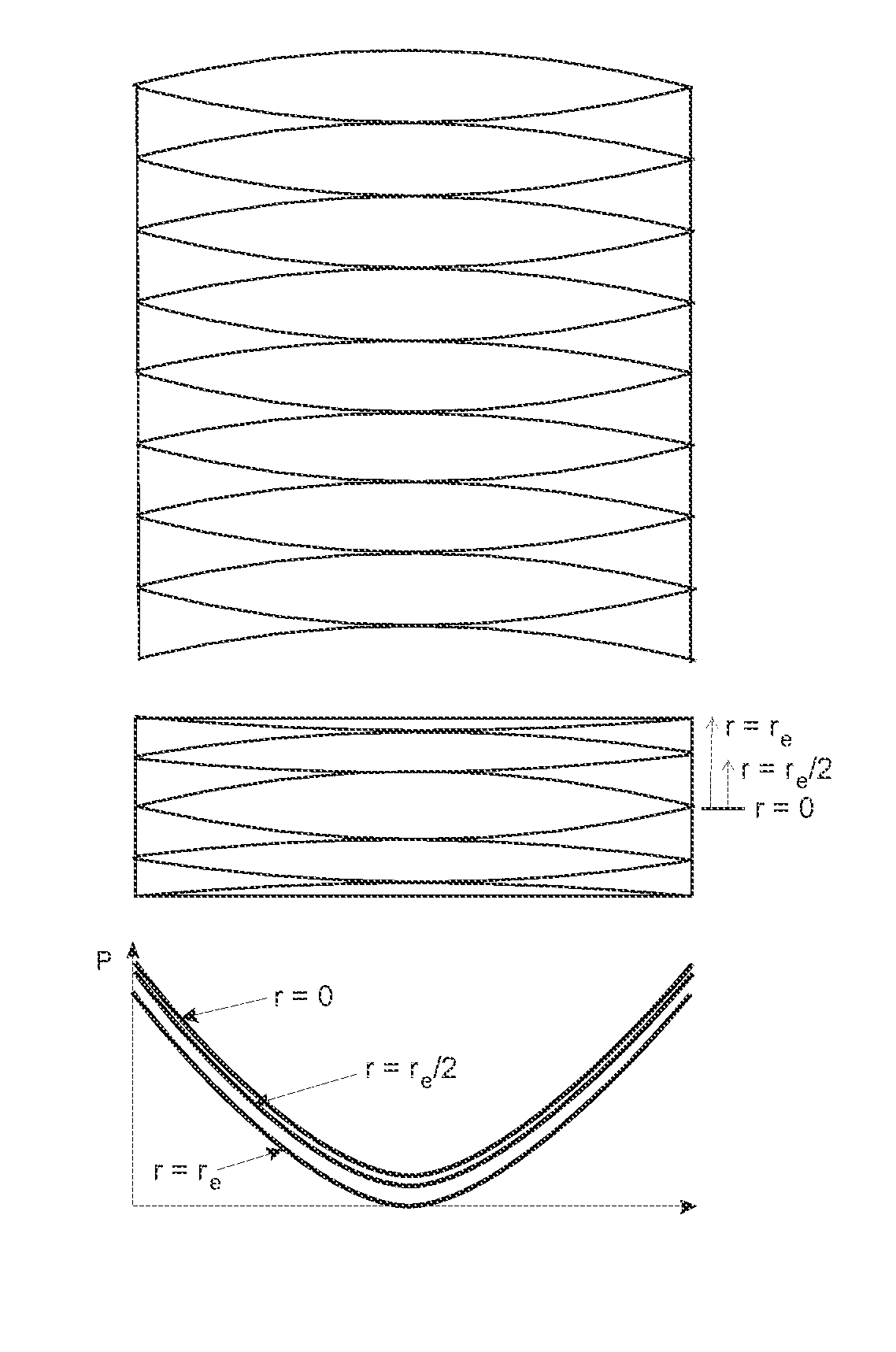
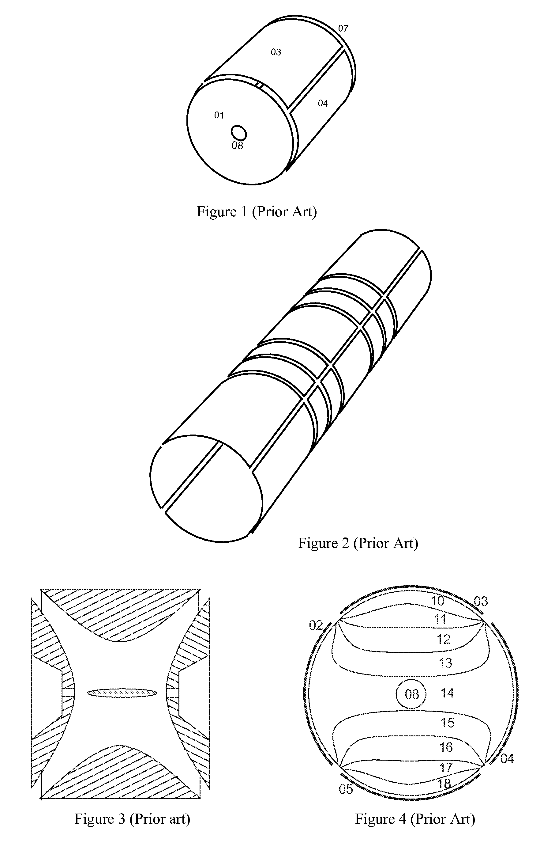
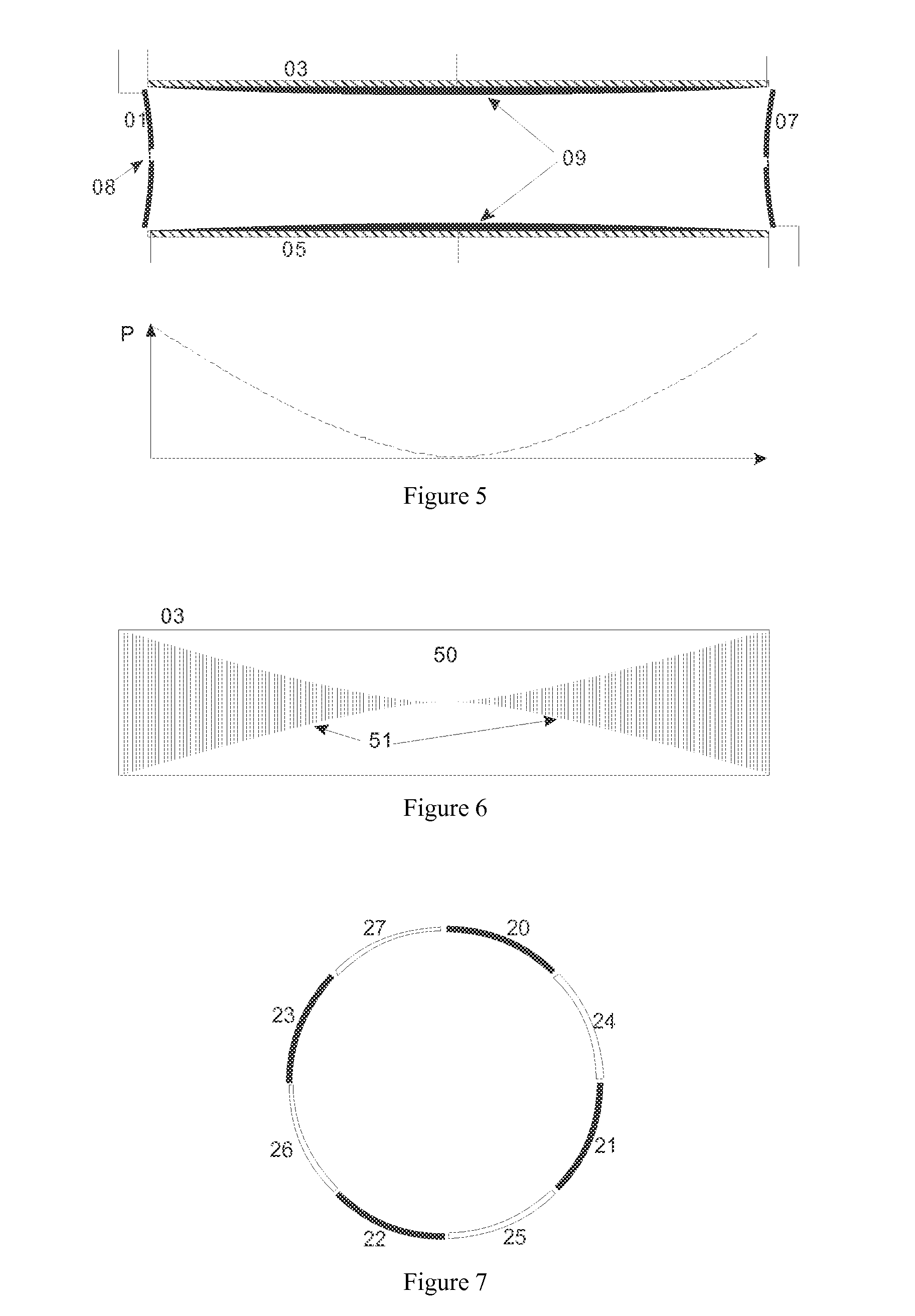
[0046]FIG. 5 exhibits schematically in the upper part, how the longitudinal sheath electrodes (03) and (05) of the ICR cell are covered with layers (09) of a resistive material. The resistances of the layers change from zero resistance in the center to high resistance at the ends; the resistance profile is symbolically indicated by a variation of the thicknesses of the layers (09). The endcap electrodes (01) and (07) are formed as rotational hyperboles, with apertures (08) to introduce the ions. The lower part of this Figure presents the parabolic potential profile P generated by a suitably applied trapping voltage along such a longitudinal electrode.

[0047]FIG. 6 shows a resistive layer (50) on electrode (03) trimmed by narrow laser cuts (51) into the wanted resistance profile.

second embodiment

[0048]FIG. 7 presents a cross section through an ICR cell according to this invention, composed by a mixture of four longitudinal electrodes with resistance layers (20) to (23) with four well conducting metal electrodes (24) to (27), the latter serving for image current detection. This ICR cell encloses a complicated potential distribution which is harmonic only on the average for orbiting ions.

third embodiment

[0049]FIG. 8 depicts a most preferred third embodiment of a cylindrical ICR measuring cell with longitudinal electrodes changing in width, not requiring any resistance layer. The sheath electrodes of the cylindrical measuring cell are divided by separating gaps with parabolic shape into eight digon-shaped and sixteen triangular sheath electrodes, each with curved sites. Geometrically, a “digon” is a surface section with two corners, in most cases defined on non-planar surfaces, but here used in combination with curved sites also for plane or cylindrical surfaces. The cylindrical cell is closed at both ends by endcap electrodes (01) which have a rotationally hyperbolic form. Apertures (08) allow for the introduction of ions in the central axis along the magnetic field lines. A single trapping voltage on the triangular sheath electrodes and on the endcaps generates the desired potential distribution in the interior, said potential distribution having a parabolic profile in the axial d...


PUM


Abstract

Devices and methods for the acquisition of mass spectra with very high mass resolution in ion cyclotron resonance mass spectrometers include cylindrical ICR measuring cells with special electrode geometries to generate harmonic trapping potentials for orbiting ions. The sheath of the cylindrical cell is divided by longitudinal gaps into a multitude of sheath electrodes, which either have to carry layers with resistance profiles able to generate parabolic voltage profiles along the sheath electrodes, or which form sheath electrodes of varying width by parabolic gaps. Orbiting ions of a given mass m / z oscillate harmonically in an axial direction with the same frequency, independent of the radius of their orbit and their oscillation amplitude. Ideally, the cylinders are closed by endcaps with rotationally hyperbolic form, divided into partial electrodes. The ions are excited by dipolar excitation fields. The orbiting ion clouds are kept together for much longer periods than was possible hitherto.

Description

FIELD OF INVENTION[0001]The invention relates to devices and methods for the acquisition of mass spectra with ultrahigh mass resolution in ion cyclotron resonance and oscillation mass spectrometers.PRIOR ART[0002]In ion cyclotron resonance mass spectrometers (ICR-MS), the charge-related masses m / z of the ions are measured by means of the frequencies of the orbital motions of clouds of coherently flying ions in ICR measuring cells, also called “Penning ion traps”, which are positioned in a homogenous magnetic field of high field strength. The orbital motion normally consists of superpositions of cyclotron and magnetron motions, the magnetron motions slightly distorting the measurement of the cyclotron frequencies. The magnetic field is generated by superconducting magnet coils cooled with liquid helium. Nowadays, commercial mass spectrometers provide usable ICR measuring cells with internal diameters of up to approximately 6 centimeters in magnetic fields of 7 to 18 tesla.[0003]In th...

Claims


Application Information

Patent Timeline
Patent Type & Authority Patents(United States)
IPC IPC(8): H01J49/28H01J49/26H01J49/20
CPCH01J49/38
Inventor NIKOLAEV, EVGENIJBOLDIN, IVANFRANZEN, JOCHEN
Owner BRUKER DALTONIK GMBH & CO KG
Why Eureka
Try Eureka