Resistive loop excitation and readout for touch point detection and generation of corresponding control signals

Active Publication Date: 2014-04-22
IRON WILL INNOVATIONS CANADA INC
View PDF17 Cites 45 Cited by
  • Summary
  • Abstract
  • Description
  • Claims
  • Application Information

AI Technical Summary

Benefits of technology

[0039]Balanced operation can also significantly reduce the likelihood of chemical migration into or from the resistive loop, since there is no net gradient to drive materials through the surrounding solution. Garments incorporating this invention can benefit from this balance through increased operational lifetimes. Balancing is especially important if the resistive loops could come into direct contact with skin or if the surrounding solution can act as a migration medium to the skin for the eroded loop material. Balancing significantly helps reduce exposure to these materials by reducing the likelihood the materials become free to ingest or absorb.
[0040]True balanced operation is also made more feasible according to the teaching of this invention by providing for the electrically active portions of the touch sensing circuit, that is the resistive loops and the sensing contacts, to be configured so they are electrically isolated and floating from the remainder of the accessible parts of the systems. If these elements are allowed to float, many potential parasitic circuits that might be formed are inhibited, which improves the ability to balance the excitation signals in a predictable way. Isolating these circuit elements also provides an important safety feature sinc

Problems solved by technology

Fixed touch points such as in the invention disclosed in U.S. Pat. No. 7,498,956 give an inflexible layout of touch points and may limit that adaptability of the glove to differe

Method used


Image

  • Resistive loop excitation and readout for touch point detection and generation of corresponding control signals
  • Resistive loop excitation and readout for touch point detection and generation of corresponding control signals
  • Resistive loop excitation and readout for touch point detection and generation of corresponding control signals

Examples


Embodiment Construction

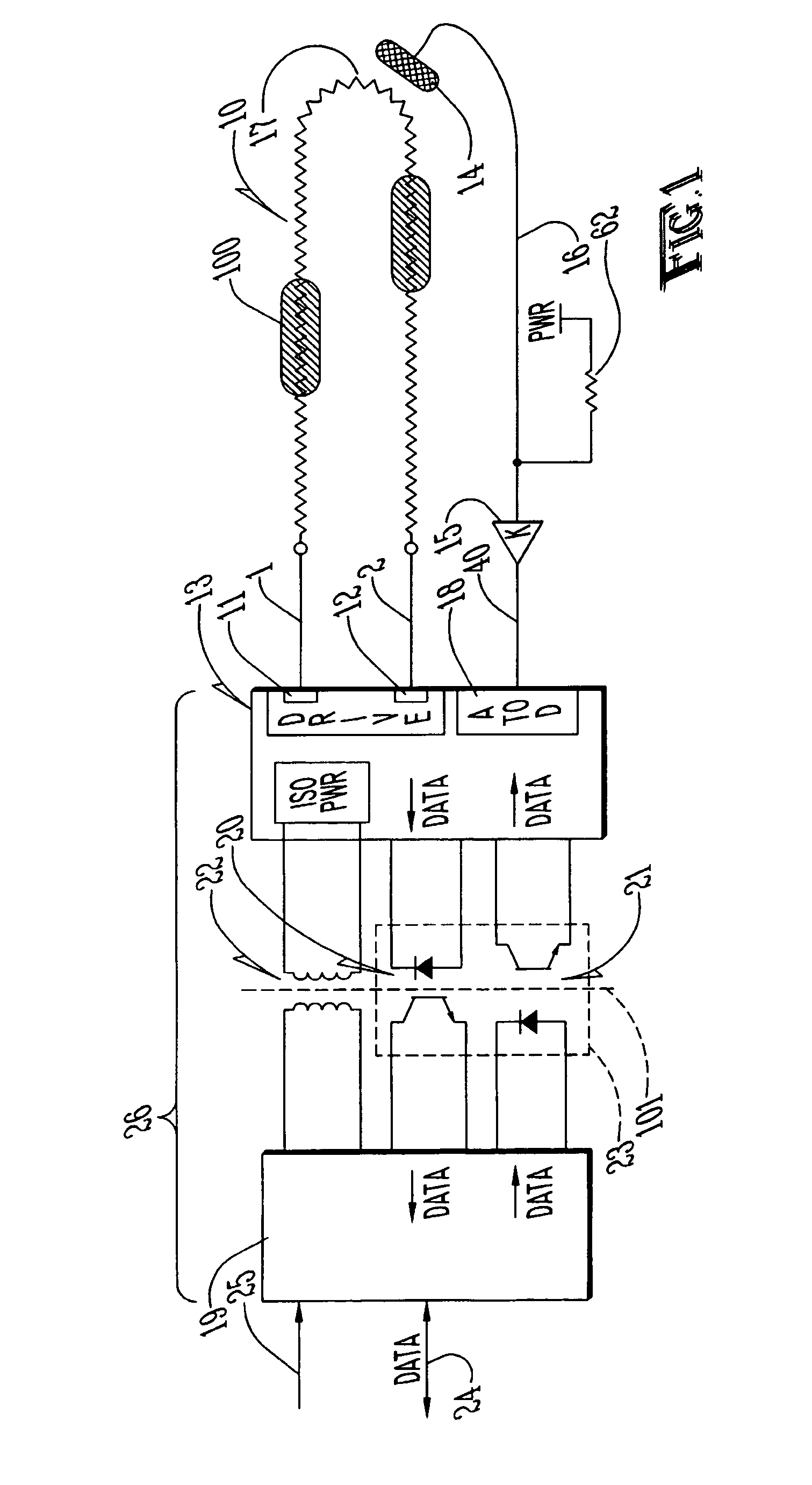
[0066]Referring to FIG. 1, a simple single loop, single sensing contact implementation of this invention can be achieved. The distal ends 1 and 2 of the resistive loop 10, are electrically connected to the excitation drive sources 11 and 12 respectively provided by the excitation scanning and analogue signal readout module 13. In one possible instance of this, simple differential voltage excitation can be produced by driving the output voltage on sources 11 and 12 to different values. This simple system is shown as using a single excited loop and a single sensing contact. The signal processing is partitioned into two sub-circuits to separate excitation scanning and analogue signal readout from measurement interpretation and control system communication functions. Electrical isolation 101 is indicated at the boundary between the signal processing sub-circuits.

[0067]It is also noted that excitation drive may be DC, AC or a constructed waveform; and that time dependent nature of excita...


PUM


Abstract

A means and method for enabling contact or touch point location detection to be implemented on a particular garment. This means and method simplifies the design of the garment by reducing the number of conductors required to interconnect the various touch points and signal processing circuitry; it provides a way to dynamically reposition or resize the effective touch point target regions; and it provides for new control capabilities by optionally allowing continuously variable user input control.

Description

CROSS REFERENCE TO RELATED APPLICATIONS[0001]This application claims the priority of the filing date of provisional patent application Ser. No. 61 / 193,307, filed on Nov. 17, 2009 by the same inventors.TECHNICAL FIELD OF THE INVENTION[0002]This invention relates to the general area of human / electronic device interface devices and more particularly to the detection and interpretation of finger touches and touch points on gloves or other garments worn on the body to interpret the actions and intent of the wearer.BACKGROUND TO THE INVENTION[0003]There are many human interface input devices for data, control and command entry into computers and other systems that are in common use. These input devices are typified by keyboards, mice, touch pads, joysticks, graphics tablets and various motion sensitive or motion activated controllers. These input devices are routinely encountered in home, office or industrial settings or in the rapidly expanding areas of console, computer and on-line gami...

Claims


Application Information

Patent Timeline
IPC IPC(8): G09G5/00G06F3/01
CPCG06F3/014G06F3/0383
Inventor FIGLEY, CURTIS B.HUNT, DARINCHICHAK, ANDREIBAIER, BRENT
Owner IRON WILL INNOVATIONS CANADA INC
Why Eureka
Try Eureka