Device and method for adjusting loop filter gain in automatic frequency controller

a loop filter and automatic frequency controller technology, applied in the direction of resonant circuit tuning, electrically long antennas, antennas, etc., can solve the problems of user equipment (ue) which accelerates in a short time period, deterioration of performance in radio communication systems, and inability to adjust the gain of the loop filter in the automatic frequency controller. achieve the effect of optimal performan

Inactive Publication Date: 2014-04-22
SAMSUNG ELECTRONICS CO LTD
View PDF9 Cites 10 Cited by
  • Summary
  • Abstract
  • Description
  • Claims
  • Application Information

AI Technical Summary

Benefits of technology

[0014]Accordingly, the present invention has been made to solve the above-mentioned problems occurring in the conventional art, and it is an object of the present invention to provide a device and a method for adjusting a loop filter gain in an automatic frequency controller, which can allow the automatic frequency controller to operate while maintaining optimal performance.
[0015]It is another object of the present invention to provide a device and a method for adjusting a loop filter gain in an automatic frequency controller, which can variably shift a loop bandwidth in accordance with a change in velocity.

Problems solved by technology

Since a carrier frequency depending on temperature gradually changes, a frequency offset is an unavoidable primary factor to cause a deterioration of performance in a radio communication system.
A timing reference of the terminal is a Temperature Crystal Oscillator (TCXO), and the timing inaccuracy is generated due to a small frequency error of the TCXO.
There is a high possibility that a user equipment (UE) which accelerates in a short time period, such as on a rapid transit railway will lose a lock state due to the bandwidth of a small loop in the tracking step.
Therefore, there is a disadvantage in that the conventional AFC having a fixed loop bandwidth through a fixed loop gain is not flexible for various circumstances.

Method used


Image

  • Device and method for adjusting loop filter gain in automatic frequency controller
  • Device and method for adjusting loop filter gain in automatic frequency controller
  • Device and method for adjusting loop filter gain in automatic frequency controller

Examples


Embodiment Construction

[0021]Hereinafter, preferred embodiments of the present invention will be described with reference to the accompanying drawings. In the following description, the same elements will be designated by the same reference numerals although they are shown in different drawings. Further, various specific definitions found in the following description, such as specific values of packet identifications, contents of displayed information, etc., are provided for a general understanding of the present invention, and it is apparent to those skilled in the art that the present invention can be implemented without such definitions. Further, in the following description of the present invention, a detailed description of known functions and configurations incorporated herein will be omitted when it may make the subject matter of the present invention rather unclear.

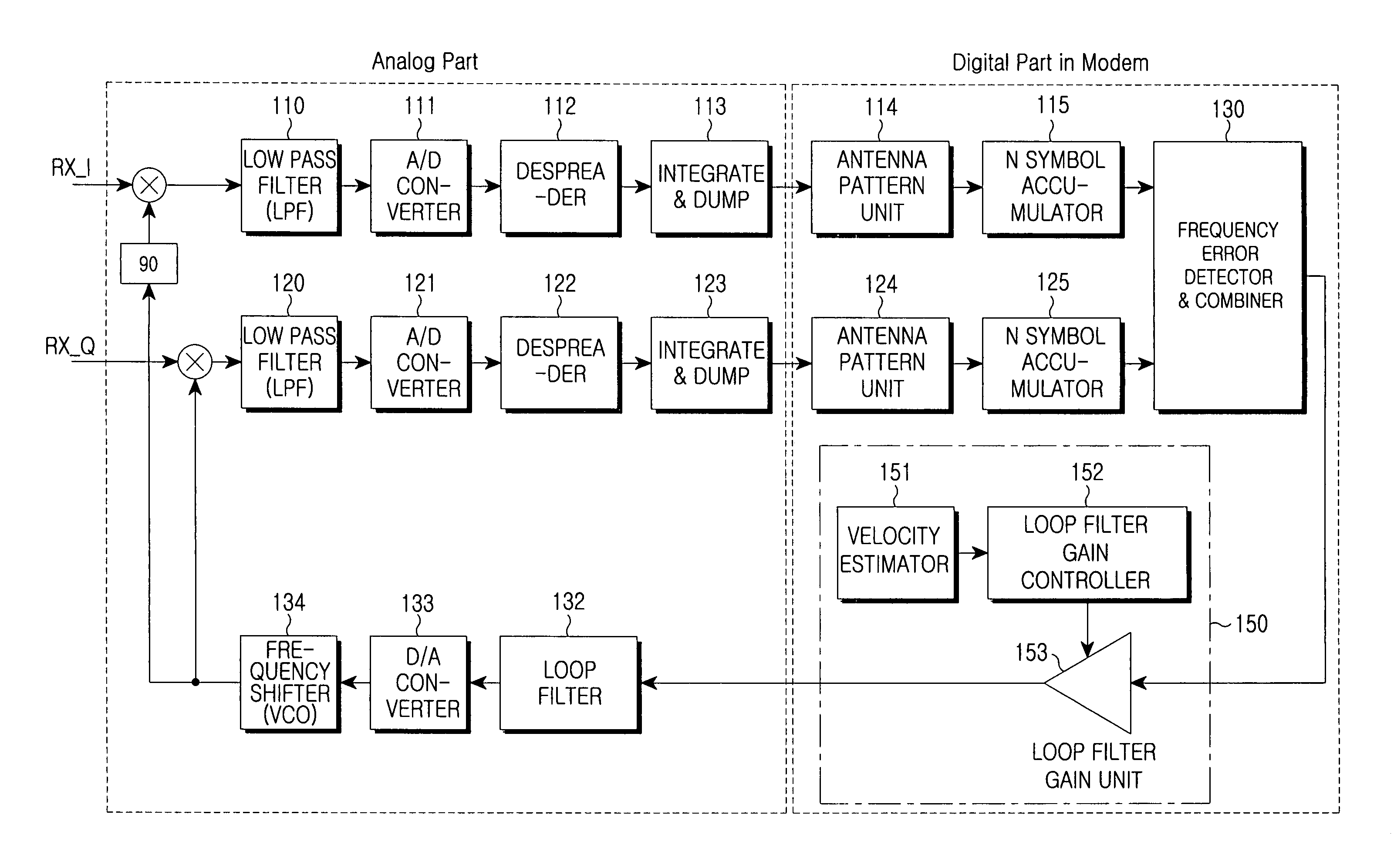
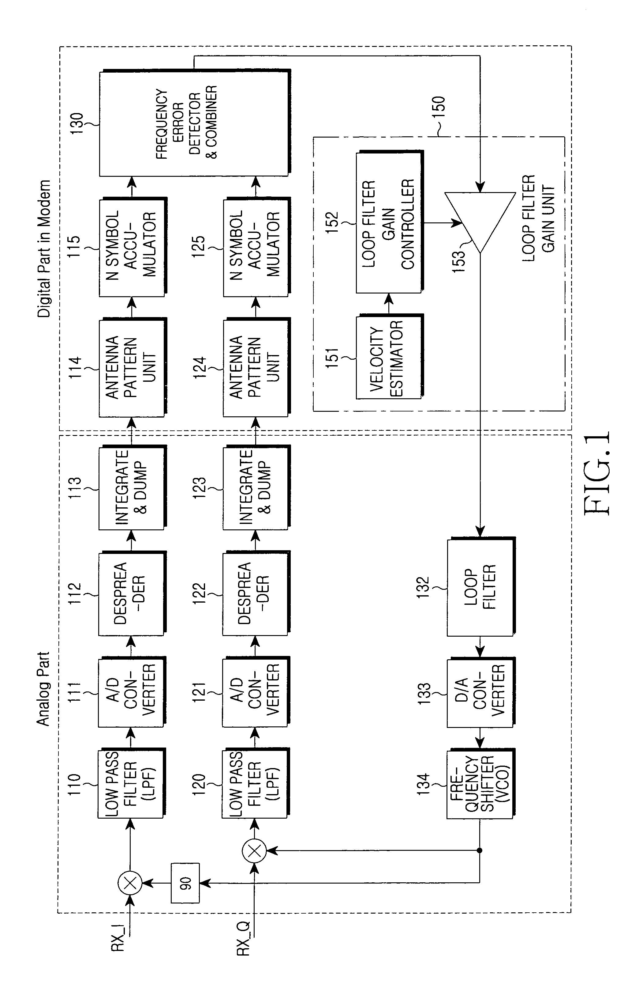
[0022]FIG. 1 is a block diagram showing a configuration of an automatic frequency controller having a loop filter gain adjusting unit ...


PUM


Abstract

Provided is a device and a method for adjusting a loop filter gain in an automatic frequency controller, which can allow the automatic frequency controller to operate while maintaining an optimal performance. The device includes a velocity estimator for estimating a change in velocity in accordance with a movement of a terminal; a loop filter gain controller for controlling a loop filter gain in accordance with a change in velocity received from the velocity estimator; and a loop filter gain unit for multiplying a loop filter gain received from the loop filter gain controller and a frequency error for output. Further, there is provided a method for adjusting a loop filter gain in an automatic frequency controller, having the steps of: estimating a change in velocity in accordance with a movement of a terminal; adjusting a loop filter gain in accordance with the estimated change in velocity; and multiplying the adjusted loop filter value and a frequency error for output.

Description

PRIORITY[0001]This application claims the benefit under 35 U.S.C. §119(a) of an application entitled “Device And Method For Adjusting Loop Filter Gain In Automatic Frequency Controller” filed in the Korean Industrial Property Office on Feb. 1, 2006 and assigned Serial No. 2006-9713, the contents of which are incorporated herein by reference.BACKGROUND OF THE INVENTION[0002]1. Field of the Invention[0003]The present invention relates generally to a device and a method for adjusting a loop filter gain in an automatic frequency controller, and in particular, to a device and a method for adjusting a loop filter gain in an automatic frequency controller, which can allow the automatic frequency controller to operate while maintaining optimal performance.[0004]2. Description of the Related Art[0005]Since a carrier frequency depending on temperature gradually changes, a frequency offset is an unavoidable primary factor to cause a deterioration of performance in a radio communication system....

Claims


Application Information

Patent Timeline
Patent Type & Authority Patents(United States)
IPC IPC(8): H04B1/40
CPCH03J7/065H03L7/00
Inventor PARK, SOO-JINLIM, CHAE-MAN
Owner SAMSUNG ELECTRONICS CO LTD
Why Eureka
Try Eureka