
Preferential loading in data centers

a data center and load technology, applied in the field of data centers, can solve the problems of multiple data centers being insufficient, service disruption, organization's image or brand may suffer, etc., and achieve the effect of optimizing the performance of the data center and minimizing the potential for service disruption

Active Publication Date: 2014-04-22
USAA
View PDF18 Cites 6 Cited by
  • Summary
  • Abstract
  • Description
  • Claims
  • Application Information

AI Technical Summary

Benefits of technology

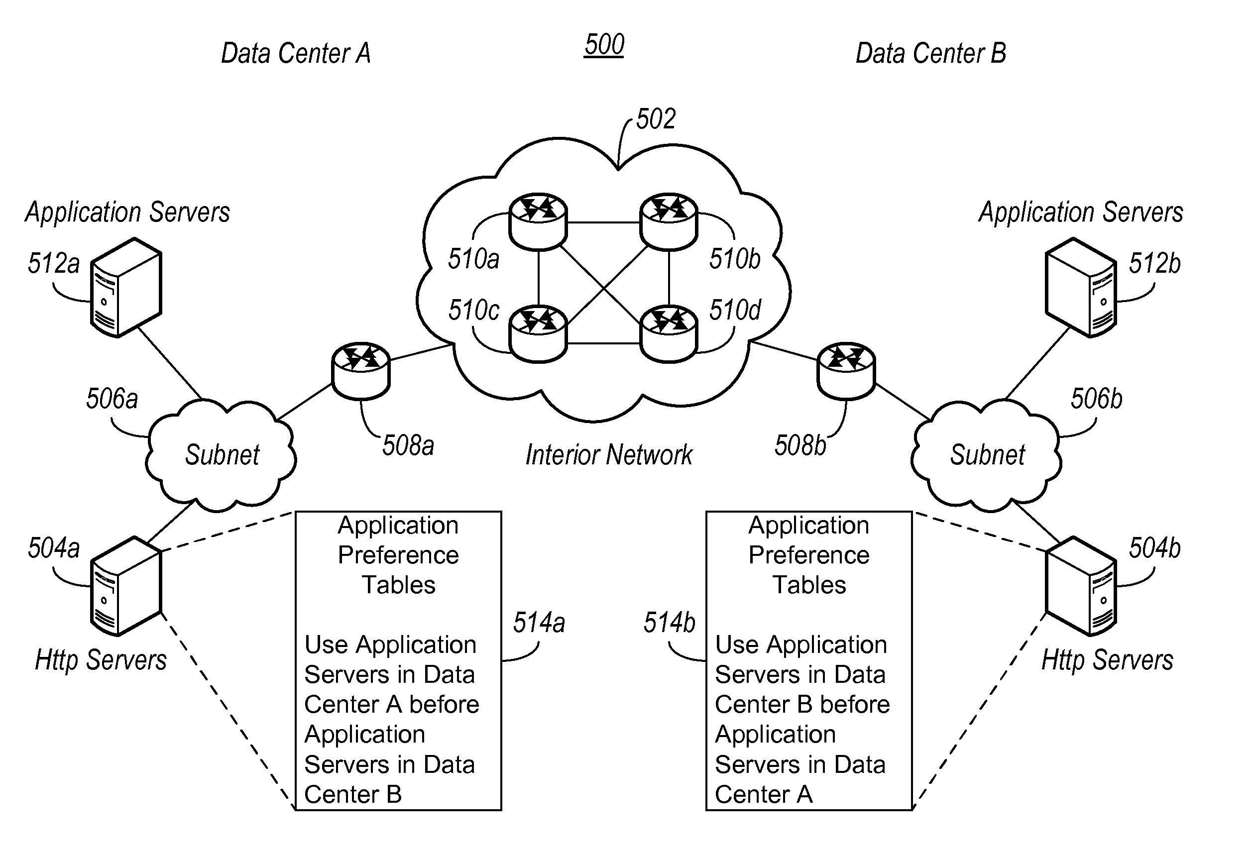
The disclosed embodiments describe an autonomous system for minimizing the likelihood that clients in one data center are routed to another data center for service without necessity. The system uses routing tables or configuration tables to decide which system to use for a specific service request, based on factors like system residency or operational criteria. This approach, known as a stovepipe arrangement, optimizes data center performance and reduces the risk of service disruption in case of failure.

Problems solved by technology

When one or more computing systems or the entire data center fails or becomes unavailable, service may be disrupted, and the organization's image or brand may suffer.
But simply having multiple data centers may not be sufficient if there are performance issues with the data centers.
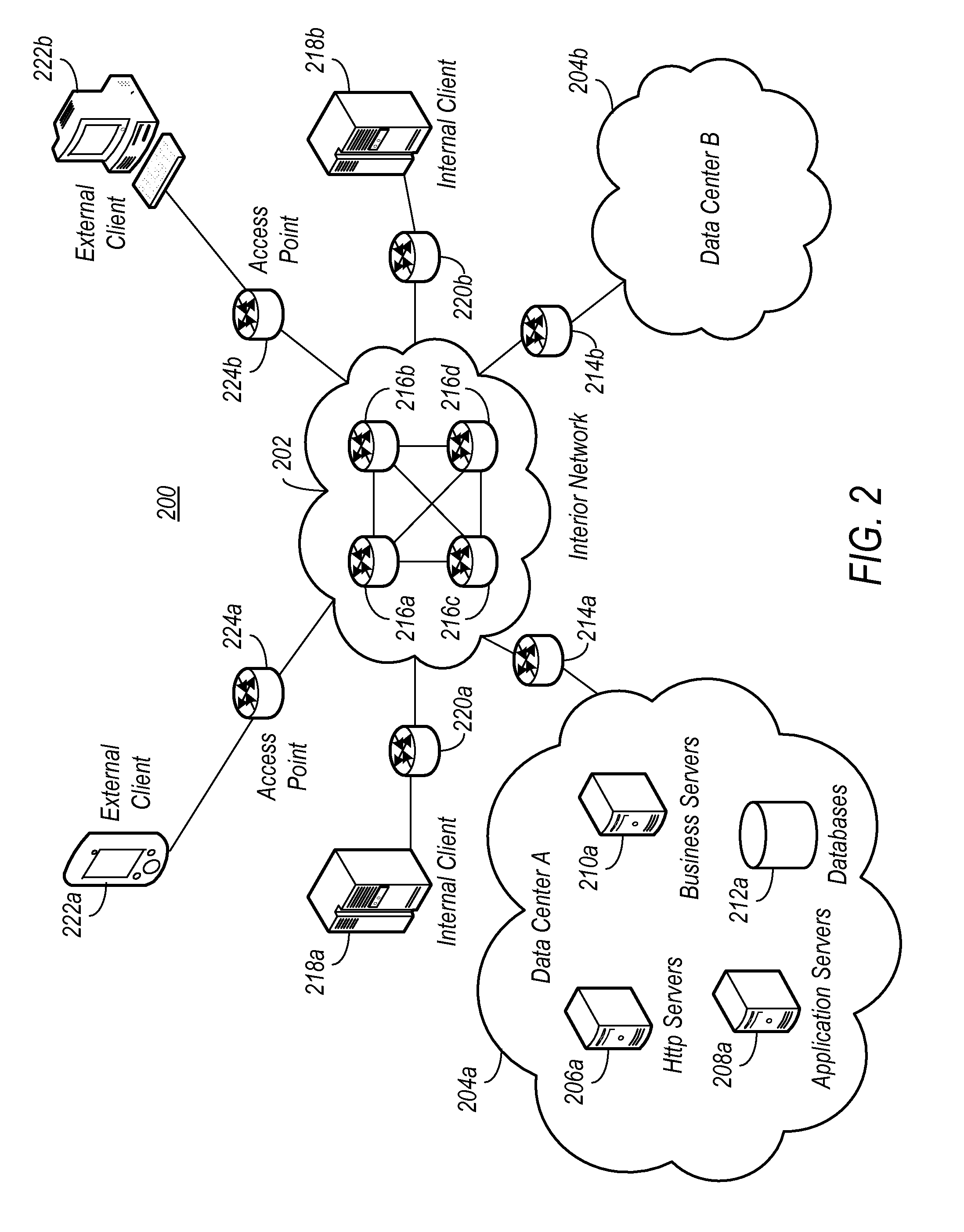
However, this physical separation may also introduce unnecessary latency, for example, when a client initially assigned to one data center is routed to another data center for service during normal operation (i.e., a non-failover situation).
Such routing of service between data centers may additionally increase the potential for disruption of service should either data centers fail relative to routing that is confined to one data center.

Method used


Image

  • Preferential loading in data centers
  • Preferential loading in data centers
  • Preferential loading in data centers

Examples


Embodiment Construction

[0020]The figures described above and the written description of specific structures and functions provided herein are not presented to limit the scope of what Applicants have invented or the scope of the appended claims. Rather, the figures and written description are provided to teach any person skilled in the art to make and use that for which patent protection is sought. Those skilled in the art will appreciate that not all features of a commercial embodiment are described or shown for the sake of clarity and understanding. Persons of skill in the art will also appreciate that the development of an actual commercial embodiment incorporating various aspects of this disclosure may require numerous implementation-specific decisions to achieve the developer's ultimate goal for the commercial embodiment. Such implementation-specific decisions may include, and likely are not limited to, compliance with system-related, business-related, government-related standards and other constraint...


PUM


Abstract

Infrastructure is disclosed for optimizing performance and minimizing errors during normal operation of replicated data centers. In some implementations, systems that are replicated in each data center under a common IP address may have service requests routed to them using routing tables that favor one of the systems. The routing tables may prefer the system that resides in the data center where the service requests originated, or they may prefer the system that meets other criteria. Other systems replicated in the data center may have service requests routed to them using configuration tables that favor one of the systems. The configuration tables may also prefer the system that resides in the data center where the service requests originated, or they may prefer the system that meets other criteria. This arrangement helps optimize performance during normal operation and minimize potential for disruption of service should one of the data centers fail.

Description

CROSS REFERENCE TO RELATED APPLICATIONS[0001]This application is related in subject matter to, and incorporates herein by reference in its entirety, each of the following: U.S. patent application 12 / 196,276 entitled “PREFERENTIAL LOADING IN DATA CENTERS,”, filed on the same date as this application; and U.S. patent application 12 / 196277 entitled “PREFERENTIAL LOADING IN DATA CENTERS,” also filed on the same date as this application.[0002]This application is related in subject matter to, and incorporates herein by reference in its entirety, each of the following U.S. patent applications (each entitled “HIGH-AVAILABILITY DATA CENTER” and filed Sep. 19, 2006): Ser. No. 11 / 533,248 (Applicant Reference No. US-0128.01); Ser. No. 11 / 533,262 (Applicant Reference No. US-0128.02); and Ser. No. 11 / 533,272 (Applicant Reference No. US-0128.03).[0003]This application is further related in subject matter to, and incorporates herein by reference in its entirety, each of the following U.S. patent ap...

Claims


Application Information

Patent Timeline
Patent Type & Authority Patents(United States)
IPC IPC(8): G06F15/173
CPCH04L67/1034H04L45/306H04L67/327G06F15/173H04L67/51
Inventor NIEDZIELSKI, DAVID MICHAELCLEMONS, JR., DONALD E.TROST, CHRISTOPHER S.
Owner USAA
Learn More