Acoustic panel

a technology of acoustic panels and acoustic panels, applied in the field of acoustic panels, can solve the problems of difficult to interpret speech, many of these options are not able to adequately blend with the desired aesthetic appearance, and many of them are difficult to understand speech, etc., to achieve the effect of reducing sound wave energy, reducing noise, and large diaphragms

Active Publication Date: 2014-04-29
BELLMAX ACOUSTIC
View PDF17 Cites 10 Cited by
  • Summary
  • Abstract
  • Description
  • Claims
  • Application Information

AI Technical Summary

Benefits of technology

[0021]In one application of the invention, the panel can be used as a wall panel of a wall structure, for example the interior wall structure of a building. The wall structure includes a frame upon which the panels may be fastened. Further, a plurality of the wall panels can be mounted to the frame to thereby provide a continuous wall surface whereby the membrane layer of each panel lies flush with the wall surface. The arrangement of apertures in clusters provides the panel with a series of resonance absorbers which are able to vibrate at maximum amplitude when imparted with sound waves of a frequency corresponding to their resonant frequency, thereby reducing sound wave energy.
[0022]As the resonance absorbers have a resonant frequency which is different to the resonant frequency of the diaphragms within the resonance absorbers, the panel is able to absorb sound wave energy across a broader range of frequencies. The resonant frequency of a resonance absorber is dependent upon the number and size of the diaphragms within the resonance absorber and the spacing between the apertures in the cluster. The resonance absorbers advantageously avoid the need for the panel to have relatively large diaphragms as each resonance absorber is able to provide comparable resonance absorption to such diaphragms. Accordingly, the panel can be provided with relatively smaller apertures and associated diaphragms in the membrane layer. This is particularly advantageous when the panel is used as an interior wall panel of a building as it enables the surface finish of the membrane layer to be maintained such that the membrane layer can mimic the flat surface appearance of the outer surface of a conventional plasterboard panel. Further the increased percentage, overall, of the smaller diaphragms increases the efficiency of absorption at the corresponding frequencies.

Problems solved by technology

In this respect if the reverberation time is too long speech can be difficult to interpret as the reverberant sound in the room acts as background noise.
However, in some instances, reverberation problems may not become apparent until construction of a building is completed.
Unfortunately, many of these options are not able to adequately blend with the desired aesthetic appearance.
Although the Bellmax panel had the desired aesthetic appearance, its ability to absorb sound wave energy once painted was found to be limited to specific frequencies.
A problem with increasing the size of the apertures is that it becomes increasing difficult for the portions of the membrane layer which overlie the apertures to retain a surface finish which can mimic that of a conventional plasterboard panel, particularly after the membrane layer is painted.
In addition, the depth of the enclosure behind the panel can not be readily increased beyond the fixed depth of the wall cavities of the building.

Method used


Image

  • Acoustic panel
  • Acoustic panel
  • Acoustic panel

Examples


Embodiment Construction

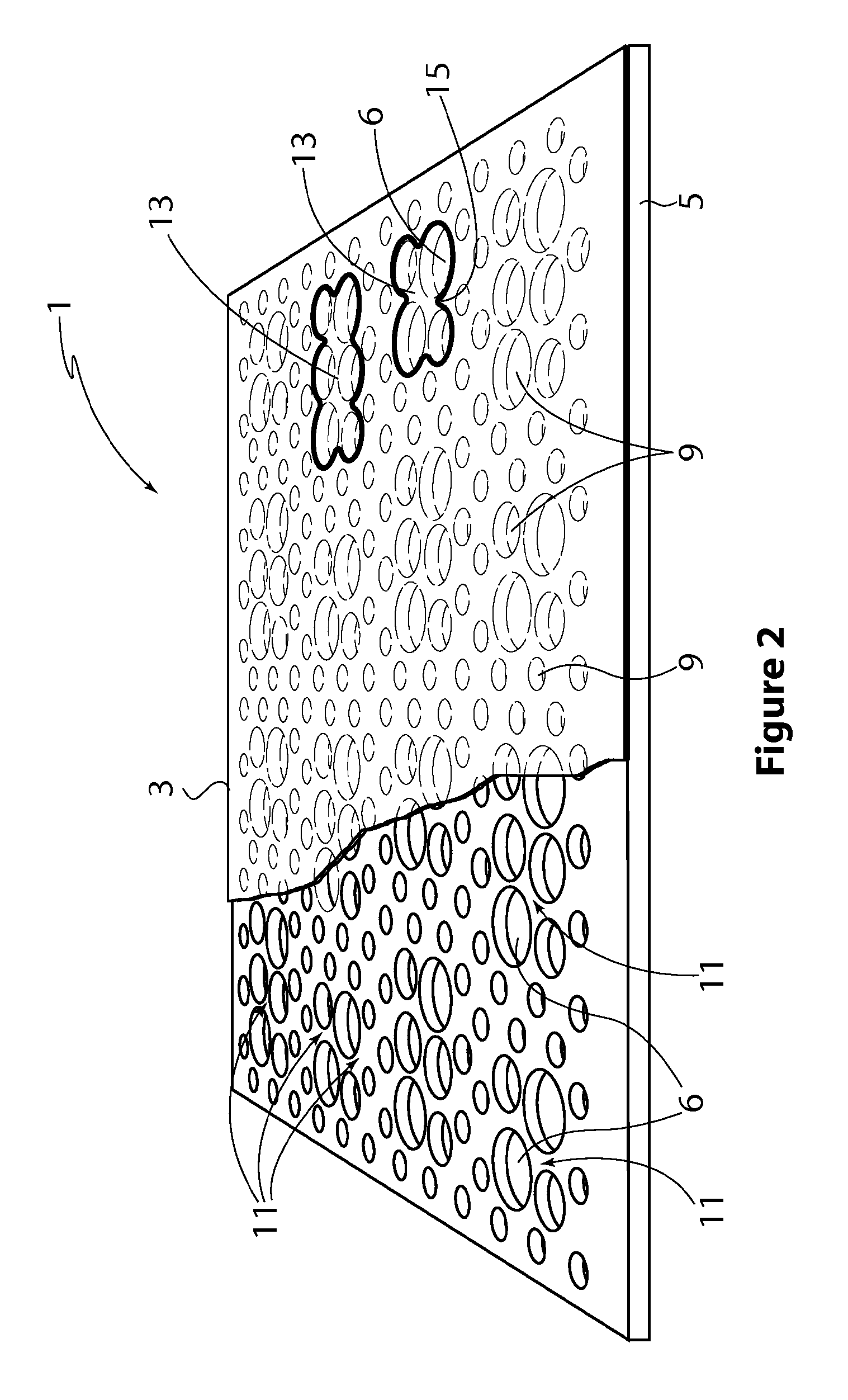
[0042]With reference to FIG. 2 of the accompanying drawings there is shown a panel 1 in accordance with an embodiment of the invention. The panel 1 includes a substantially air impermeable membrane layer 3 and a layer 5 having apertures 6 therein. The apertures 6 in the layer 5 preferably define a plurality of passageways which extend through the layer 5, hereinafter referred to in this section as the apertured layer 5. A section of the membrane layer 3 has been removed from the panel 1 in FIG. 2 such that the apertures 6 can be more clearly seen. Each portion of the membrane layer 3 which overlies a passageway defines a diaphragm 9 which is able to vibrate in response to sound waves incident on the membrane layer 3 and thereby absorb at least part of the sound waves energy. In this respect, each diaphragm 9 has a resonant frequency at which the diaphragm 9 will vibrate at maximum amplitude when imparted with sound waves of a frequency which corresponds to the diaphragm's resonant f...


PUM

PropertyMeasurementUnit
distanceaaaaaaaaaa
diameteraaaaaaaaaa
diameteraaaaaaaaaa

Abstract

A panel (1) including a substantially air impermeable membrane layer (3) and a layer (5) having apertures (6) therein, wherein each portion of the membrane layer (3) which overlies an aperture (6) defines a diaphragm (9) which is able to vibrate in response to sound waves incident on the membrane layer (3) and thereby absorb at least part of the sound waves' energy, at least some of the apertures (6) being arranged in clusters (11) whereby the greatest distance between adjacent apertures within a cluster (11) is less than the distance between (i) any one of the apertures (6) within the cluster (11) and (ii) any aperture (6) outside of the cluster (11), each region of the panel (1) defined by an outer periphery of a cluster (11) forming a resonance absorber (13) which is able to vibrate in response to sound waves and thereby absorb at least part of the sound waves energy, wherein at least one resonance absorber (13) is able to provide sound absorption at a frequency which is different to the frequency of resonance of at least one of the individual diaphragms (9).

Description

CROSS-REFERENCE TO RELATED APPLICATIONS[0001]The present patent application is a nationalization of International application No. PCT / AU2010 / 001395, filed Oct. 21, 2010, published in English, which is based on, and claims priority from, Australian Application No. 2009905 filed Oct. 21, 2009 and Australian Application No. 2010903103, filed Jul. 13, 2010, all of which are incorporated herein by reference in their entireties.FIELD OF THE INVENTION[0002]The present invention relates to an acoustic panel which is acoustically absorbent relative to conventional air impermeable panels, for example plasterboard or drywall, across a broad range of frequencies. The panel according to the present invention is suited for lining an interior wall or ceiling of a building in the same manner as conventional plasterboard panels. The panel according to the invention is also suitable for lining other structures that are required to absorb noise. Various forms of the panel are also suitable for automot...

Claims


Application Information

Patent Timeline
Patent Type & Authority Patents(United States)
IPC IPC(8): E04B1/82
CPCB32B3/266B32B5/18B32B7/12E04B1/86E04B2001/8461E04B2001/8476E04B2001/848E04B2001/8485G10K11/172B32B5/022B32B5/142B32B15/046B32B15/08B32B15/12B32B15/14B32B15/20B32B27/065B32B27/10B32B27/12B32B27/304B32B27/306B32B27/32B32B27/322B32B27/36B32B29/005B32B29/007B32B29/02B32B2255/12B32B2255/20B32B2262/0253B32B2262/0276B32B2262/101B32B2262/108B32B2266/0285B32B2266/08B32B2307/10B32B2307/102B32B2307/724B32B2307/7242B32B2607/00
Inventor BORRONI, MARK
Owner BELLMAX ACOUSTIC
Why Eureka
Try Eureka