Cemented carbide insert as well as a cemented carbide blank for the manufacture of such cutting inserts

a technology of cemented carbide and cutting inserts, which is applied in the direction of cutting inserts, manufacturing tools, shaping cutters, etc., can solve the problems of reducing the ability of cutting inserts to machine workpieces in a dimensionally accurate way, increasing grinding surface and grinding depth, and increasing costs

Active Publication Date: 2014-04-29
SANDVIK INTELLECTUAL PROPERTY AB
View PDF25 Cites 1 Cited by
  • Summary
  • Abstract
  • Description
  • Claims
  • Application Information

AI Technical Summary

Benefits of technology

[0008]The present invention aims at obviating the above-mentioned problems and at providing an improved cemented carbide insert of the type that requires simultaneous precision grinding of surfaces on an extremely hard inset as well as surrounding surfaces of cemented carbide. Therefore, an object of the invention is to provide a cemented carbide insert, in particular a turning insert, e.g. of the type that is disclosed in U.S. Pat. No. 7,387,474, which can be made with an inset difficult to grind of an extraordinary hard nature, and which in spite of said inset can be precision ground in a simple and cost-effective way.

Problems solved by technology

All forms of grinding of cemented carbide inserts are costly.
The rule is that the cost increases with increasing grinding surface and increasing grinding depth.
Therefore, if a cutting insert would be impaired by even the slightest defective grinding, e.g. in transitions between different surfaces on the cutting insert, the ability of the cutting insert to machine the workpiece in a dimensionally accurate way would diminish.
If the user would suspect that a cutting insert is defect, there is a risk that he directly discards the same.
Already grinding of genuine cemented carbide inserts, i.e., cutting inserts exclusively made from cemented carbide, is accordingly a delicate task, in particular if the pressing / sintering and the grinding, respectively, of the cutting inserts are carried out by different actors in different works.
The task becomes even more delicate if the cemented carbide inserts in addition are to be provided with particularly hard insets precisely in the area of the cutting edges.
Although such insets usually are only of millimeter size, they make the grinding significantly more difficult, not only in respect of time-consumption and cost, but also in respect of the quality of the finish-ground surfaces, in particular in transitions between the individual inset and the surrounding cemented carbide.
A disadvantage of this cutting insert is, however, that the manufacture requires grinding of large cemented carbide surfaces in addition to the relatively small surfaces on the inset that are required to delimit the cutting edge.
This means that unnecessary energy and time are consumed to grind in the inset while ensuring neat transitions between the inset and the surrounding cemented carbide.

Method used


Image

  • Cemented carbide insert as well as a cemented carbide blank for the manufacture of such cutting inserts
  • Cemented carbide insert as well as a cemented carbide blank for the manufacture of such cutting inserts
  • Cemented carbide insert as well as a cemented carbide blank for the manufacture of such cutting inserts

Examples


Embodiment Construction

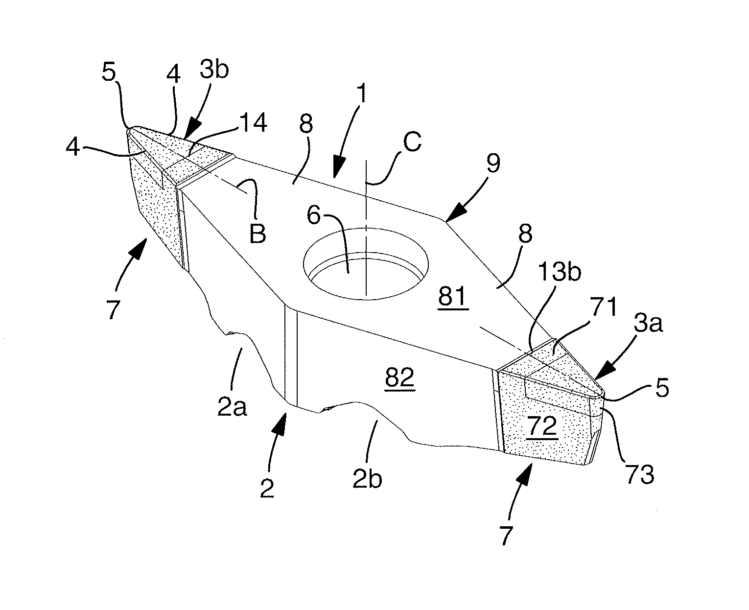
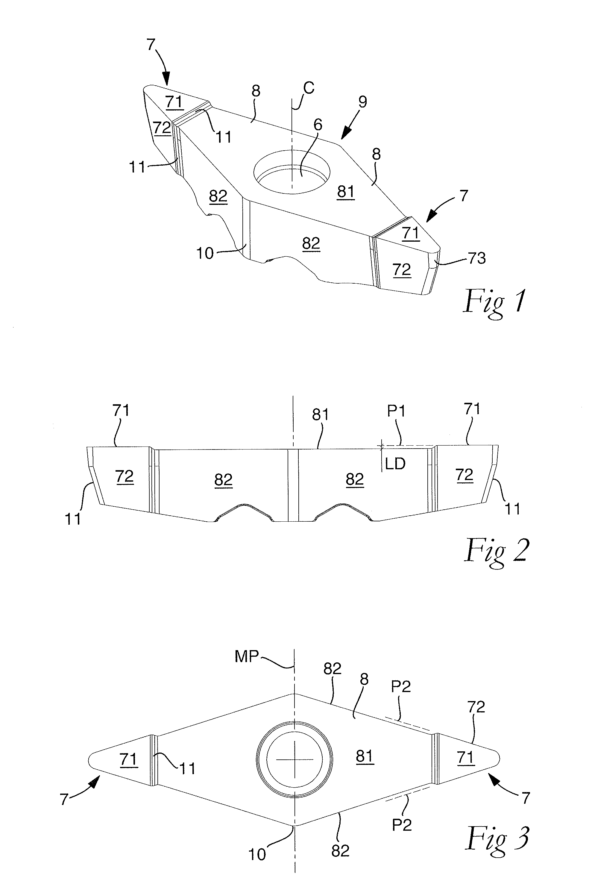
[0032]A ready for use, ground cutting insert according to an embodiment of the invention is shown in FIGS. 8 and 9. In these figures, it is seen that the cutting insert includes an upper side generally designated 1, an under side 2, and a number of side surfaces extending between the same, which will be described in more detail below. The cutting insert has a rhombic basic shape and includes two diametrically opposed cutting edges 3a, 3b, each one of which includes two main edges 4 and a secondary or nose edge 5, against which the main edges 4 converge. The main edges 4 are straight, while the nose edge 5 is rounded and has a suitable radius. The angle of convergence or the so-called nose angle may vary, but amounts to 35° in the example according to FIGS. 1-9. Between the upper and under sides 1, 2, a through hole 6 extends, the center axis C of which represents the center of the cutting insert. It should also be pointed out that the individual nose edge 5 is intersected by a bisec...


PUM

PropertyMeasurementUnit
nose angleaaaaaaaaaa
angleaaaaaaaaaa

Abstract

A cemented carbide insert, including an upper side, an under side, a plurality of side surfaces extending between the upper side and the underside, and an inset including a cutting edge. The cutting edge includes a nose edge and two main edges converging toward the nose edge. The inset is formed of a material that is harder than the cemented carbide, and is countersunk in the surrounding cemented carbide and co-ground with the surrounding cemented carbide. The inset is arranged in a front, wedge-shaped head delimited by one chip surface and two clearance surfaces running along the main edges. The inset transforms into an adjacent body part via limiting surfaces situated inside imaginary planes in the extension of the chip surface and the clearance surfaces.

Description

[0001]This application claims priority under 35 U.S.C. §119 to Swedish Patent Application No. 1050557-6, filed on Jun. 2, 2010, which is incorporated by reference herein in its entirety.FIELD OF THE INVENTION[0002]The present invention relates generally to a cemented carbide insert of the type that includes an upper side, an under side, and a number of side surfaces extending between the same as well as at least one cutting edge, which includes a nose edge and two main edges converging toward the same and is included in an inset, which includes a material that is harder than the cemented carbide, and which is countersunk in the surrounding cemented carbide and co-ground with the same. In a second aspect, the invention also relates to a cemented carbide blank for the manufacture of cutting inserts of the kind in question.BACKGROUND OF THE INVENTION[0003]By U.S. Pat. No. 7,387,474, an indexable turning insert is previously known, which has a rhombic basic shape and includes two diamet...

Claims


Application Information

Patent Timeline
Patent Type & Authority Patents(United States)
IPC IPC(8): B23B27/14
CPCB23B2226/315B23B2200/165B23B27/145B23B2226/125B23B2240/11Y10T407/24Y10T407/235Y10T407/23Y10T428/24479Y10T407/26B23B27/14B23B27/16B23P15/28B23B27/18B23B27/20
Inventor EDLER, DANIELNORDIN, ELISABETH
Owner SANDVIK INTELLECTUAL PROPERTY AB
Why Eureka
Try Eureka