Aerostatic bearing and method for production thereof

Inactive Publication Date: 2014-05-06
BSH BOSCH & SIEMENS HAUSGERAETE GMBH +1
View PDF7 Cites 4 Cited by
  • Summary
  • Abstract
  • Description
  • Claims
  • Application Information

AI Technical Summary

Benefits of technology

[0006]The object of the invention is to specify an aerostatic bearing which is both mechanically robust and also able to be produced cost effecti

Problems solved by technology

The method is thus essentially only able to be used cost effectively for small widths of the guide element.
A further problem of the conical hole shape is that, with a bearing under a heavy load, the bearing plate has have a high wall thickness to be sufficiently stable in shape.
To safely avoid the bearing bodies coming into contact however, a high density of nozzles is simultaneously needed, which, as a result of their conical form, greatly weaken the bearing plate or restrict the maximum wall width able to be realized.
A further disadvantage of an aeros

Method used


Image

  • Aerostatic bearing and method for production thereof
  • Aerostatic bearing and method for production thereof
  • Aerostatic bearing and method for production thereof

Examples


Example

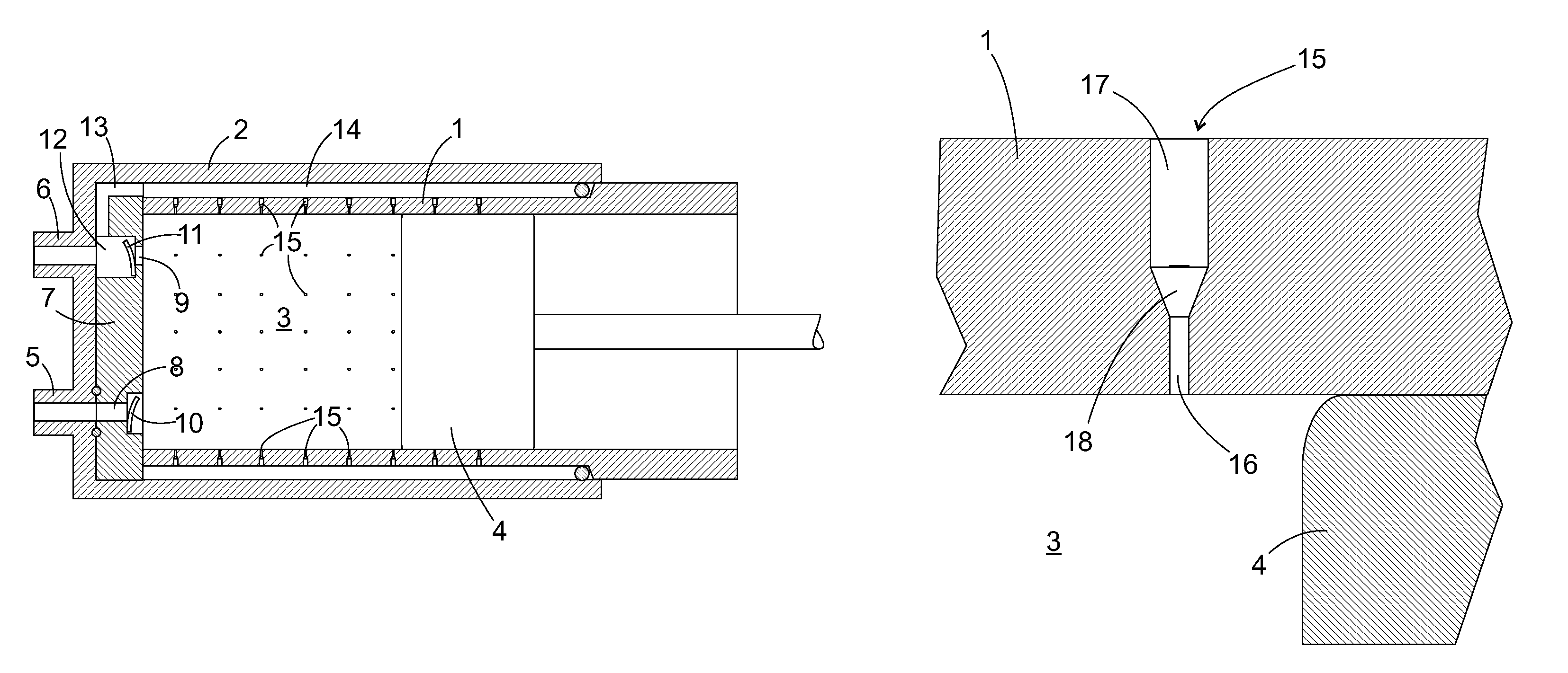
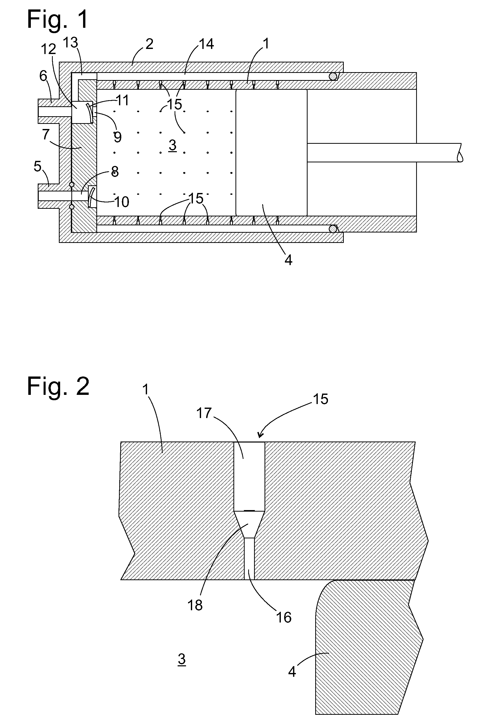
[0031]The aerostatic bearing shown in an axial section in FIG. 1 comprises a cylindrical tube section 1 and a cup 2 turned in around one end of the tubular section 1, which together delimit a compressor chamber 3 of a linear compressor, and a piston 4 able to be moved backwards and forwards in the tubular section 1. At the base of the cup are located an inlet connection piece 5 and an outlet connection piece 6. A valve plate 7 within the cup 2 forms an end face side of the compressor chamber 3. The valve plate 7 has holes 8, 9 lining up with the connection pieces 5, 6 which each accommodate a non-return valve 10, 11. The non-return valves 10, 11 are each formed by elastic tongues which in the relaxed state rest against a valve seat formed by a shoulder of the hole 8 or 9 respectively; other designs of non-return valve are also considered.

[0032]From a chamber 12 arranged between the non-return valve 11 and the outlet connection 6 of the hole a connection line 13 extends to an annular...


PUM

PropertyMeasurementUnit
Lengthaaaaaaaaaa
Lengthaaaaaaaaaa
Fractionaaaaaaaaaa

Abstract

An aerostatic bearing and a linear compressor that includes the aerostatic bearing. In an exemplary embodiment, the aerostatic bearing includes a guide element including holes, and a body structured to move along a surface of the guide element. The holes may include a first section close to the body, of which at least one part area features a cross-sectional surface substantially constant over its entire length which is smaller towards the body than another cross-sectional surface of an area away from the body. A method for producing a hole in an element, using a laser beam, for producing the aerostatic bearing is also disclosed.

Description

BACKGROUND OF THE INVENTION[0001]The present invention relates to an aerostatic bearing and to a method for producing micro holes which is especially applicable to the production of the aerostatic bearing.[0002]Aerostatic bearings are based on air or another gas being blown in between two bearing bodies. The resulting dynamic pressure means that a gap is produced between the two bearing bodies, i.e. direct contact between the bearing bodies is avoided. It is thus possible to carry out relative movements between the bearing bodies with low frictional forces and thereby to realize a low-wear bearing with high efficiency. A supply channel for feeding the air or another gas into the bearing gap runs through one of the two bearing bodies, referred to below as the guide element. To maintain the gas cushion between the bearing bodies work must continuously be done. To keep the gas consumption—and thereby the energy consumption—of the bearing low or to achieve a high bearing force of the be...

Claims


Application Information

Patent Timeline
IPC IPC(8): F16J10/04
CPCB23K26/0626F16C29/025F16C32/0622B23K26/388B23K26/389
Inventor GIACCHI, MARCOGRAF, ULRICHMAYERSHOFER, CHRISTIANOSTRINSKY, JORNSCHUBERT, JAN-GRIGORWOLF, ANDREAS
Owner BSH BOSCH & SIEMENS HAUSGERAETE GMBH
Why Eureka
Try Eureka