[0007] It is an object of the present invention to provide a periscope that is easy to manufacture and cost effective to produce.
[0009] It is another object of the present invention to provide a periscope where optical viewing may be achieved by one or many users.
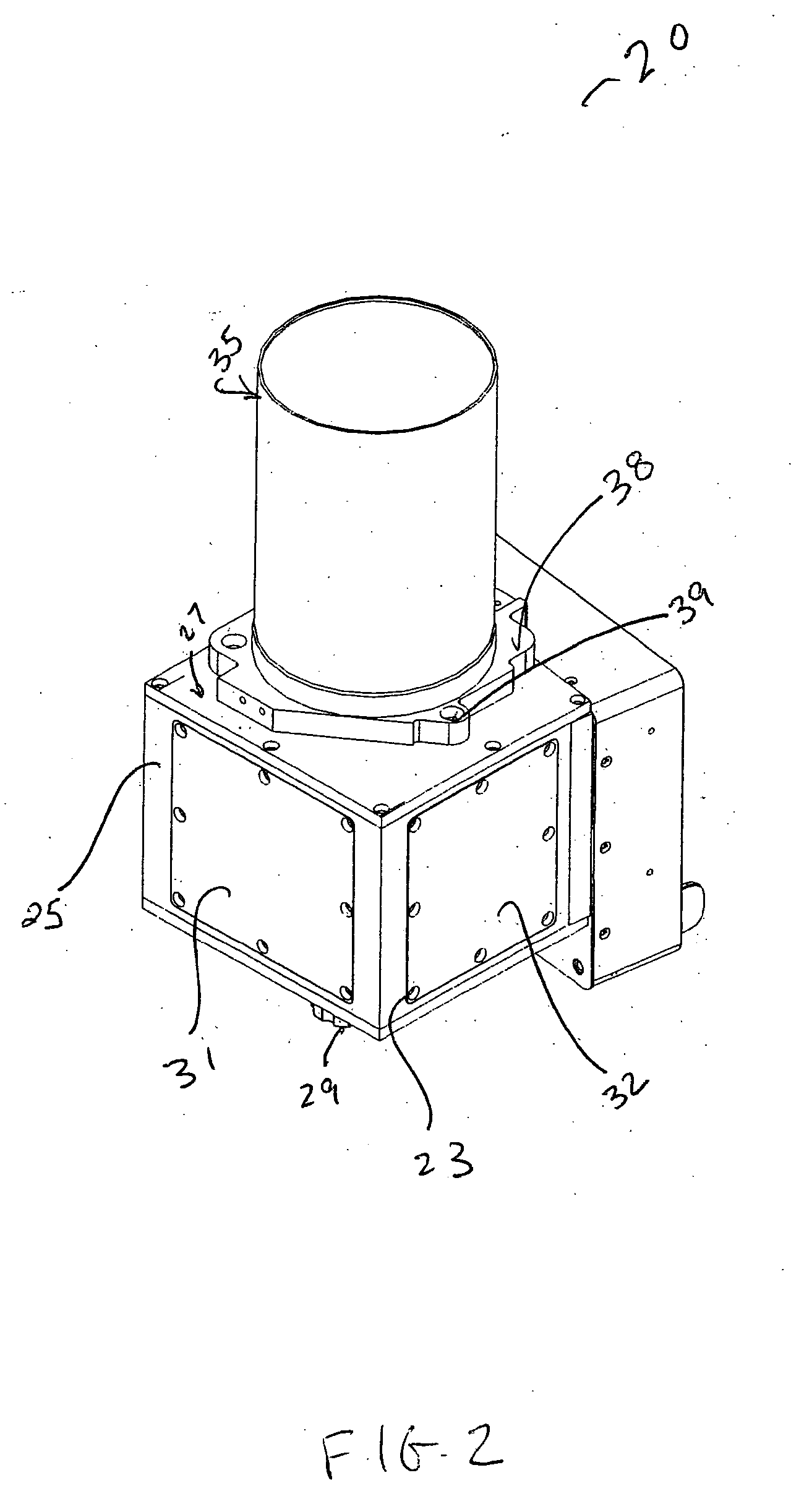
[0010] It is still another object of the present invention to provide a periscope with a housing that is capable of containing all the advanced circuitry needed, and a housing that will not capture too much space, thus providing the viewer ample room to move.
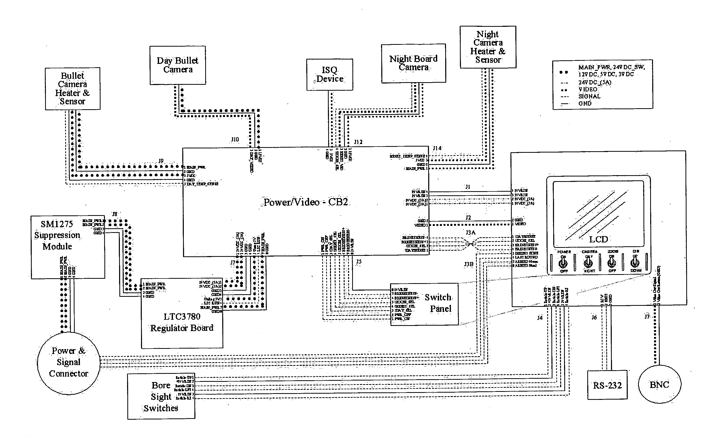
[0012] The present invention includes a periscope that allows for better day and night time viewing. In most periscopes used today, one camera is implemented. In the present invention two cameras are implemented, one used for day time viewing, the bullet camera, and one used for night time viewing, the night board camera. In addition, cameras used in most periscopes today implement a 25 mm
image intensifier tube; some periscopes do not even implement an
intensifier tube. The periscope of the present invention utilizes an 18 mm
image intensifier tube, which up until now, has never been used in periscopes. Generally, ANVIS, aviator's
night vision imaging system, are primarily used in conjunction with goggles. The 18 mm image
intensifier tube provides the present invention with the capability of detecting and amplifying
low light level images during night time viewing and surveillance, under
moonlight or
starlight. In addition, for very low light levels the 18 mm image
intensifier may be equipped with two or three microchannel plates to create an image by detecting single photons. Furthermore, one may implement a high speed gate with the 18 mm image intensifier tube to capture a fast event such as
motion analysis of high speed moving objects and
fluorescence lifetime imaging. The viewing panel of the present invention is a
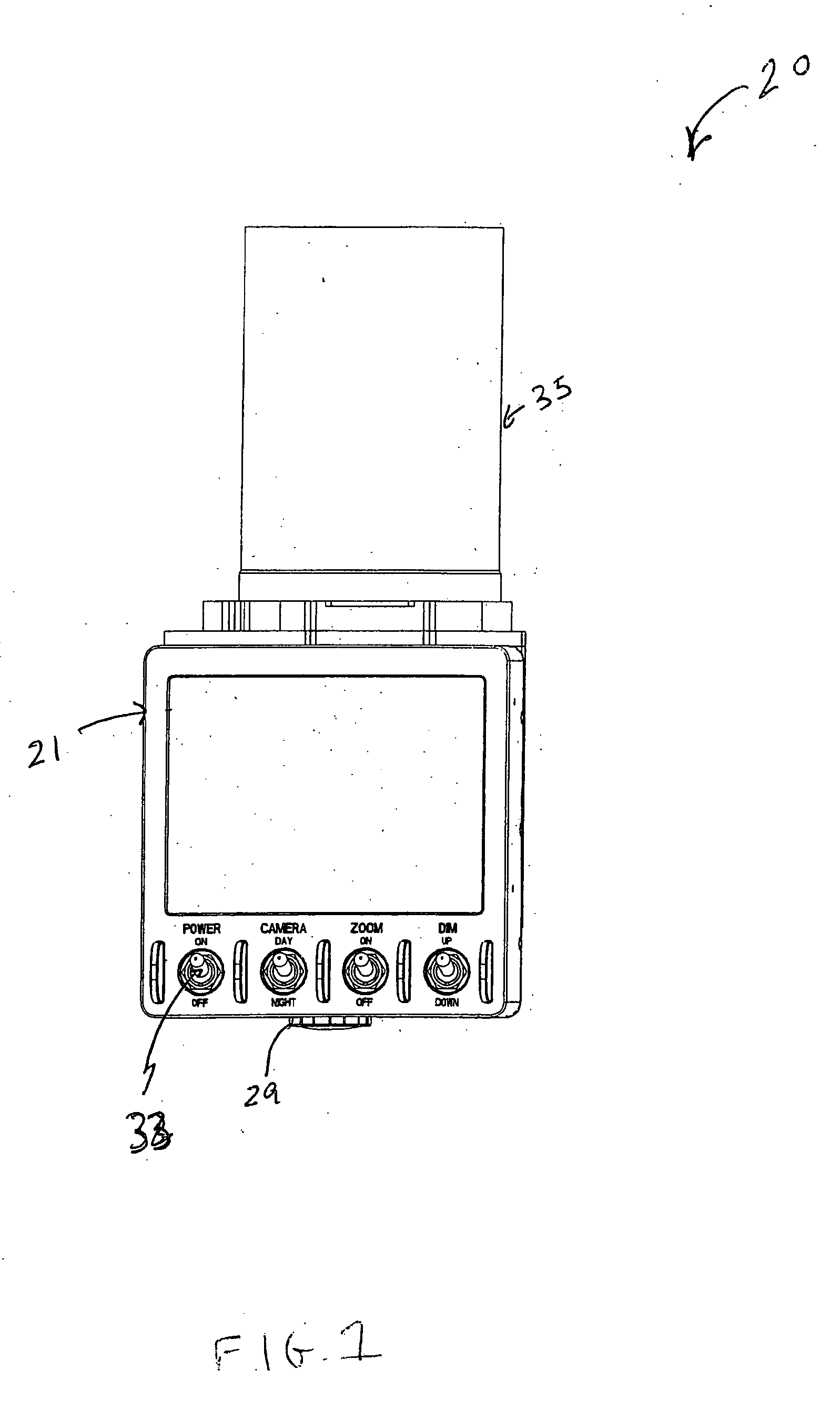
high resolution flat panel display, which has electronic recticles that are in focus at all ranges. The flat panel viewing screen is also fatigue free, which results in improved gunner performance. The present invention also implements
cutting edge circuitry which maintains proper LCD and camera operation at temperatures at or below 32° Fahrenheit. The advanced circuitry compares
on board temperatures to ambient temperatures, and when the temperature falls below a predetermined
threshold temperature, small amounts of current are allowed to flow to around the optical viewing equipment. In addition, unlike previous periscopes, the present invention allows for viewing of the optical display via a state of the art flat panel screen, which as mentioned previously has electronically generated reticles always in focus. Furthermore, the optical display from the periscope may be viewed by others in real time, i.e. no time
delay, via a video channel connection, which may be transmitted to others via
radio transmission and or electronically, to another LCD, or other display apparatuses, such as a CRT,
plasma T.V. or the like. The present invention also allows the user to take still shots from the display screen if desired. One may also implement a wide variety of overlays with the flat panel screen. The present invention also implements a state of the art
laser range finder. In addition, the housing which contains most of the circuitry is smaller then prior art, thus allowing for an easier viewing environment. The
decreased size of the housing is a result of more sophisticated electronic circuitry. The present invention is a necessary and much needed improvement for military personal, especially with the United States involvement overseas.

