Flow rate detection device having anti-undercurrent material

a detection device and flow rate technology, applied in measurement devices, volume/mass flow measurement, instruments, etc., can solve the problems of reducing the accuracy of flow rate detection and insufficient prevention of undercurrent, and achieve the effect of preventing the reduction of flow rate detection accuracy

Inactive Publication Date: 2014-05-13
MITSUBISHI ELECTRIC CORP
View PDF21 Cites 1 Cited by
  • Summary
  • Abstract
  • Description
  • Claims
  • Application Information

AI Technical Summary

Benefits of technology

[0008]The present invention has been made to solve the above-mentioned problem, and it is therefore an object thereof to provide a flow rate detection device capable of suppressing an undercurrent, which flows around and into a gap between a sensor element and a support fitting portion, to thereby prevent a reduction in flow rate detection accuracy.
[0010]The flow rate detection device according to the present invention is capable of suppressing the undercurrent, which flows around and into the gap between the sensor element and the support fitting portion, to thereby prevent the reduction in flow rate detection accuracy.

Problems solved by technology

In the flow rate detection device having the cantilever support structure as disclosed in Japanese Patent Application Laid-open No. 09-026343, a fluid to be measured flows only on a front surface of the sensor element in a low flow rate range, whereas in a high flow rate range, the fluid to be measured flows into a gap between the sensor element and the support fitting portion as well (hereinafter, this flow is referred to as “undercurrent”), which leads to a problem of reduced accuracy in flow rate detection.
However, when the fluid to be measured is guided into the slot, part of the fluid sometimes flows around and into the gap between the sensor element and the support fitting portion, and the undercurrent cannot be prevented sufficiently.

Method used


Image

  • Flow rate detection device having anti-undercurrent material
  • Flow rate detection device having anti-undercurrent material
  • Flow rate detection device having anti-undercurrent material

Examples


first embodiment

[0030

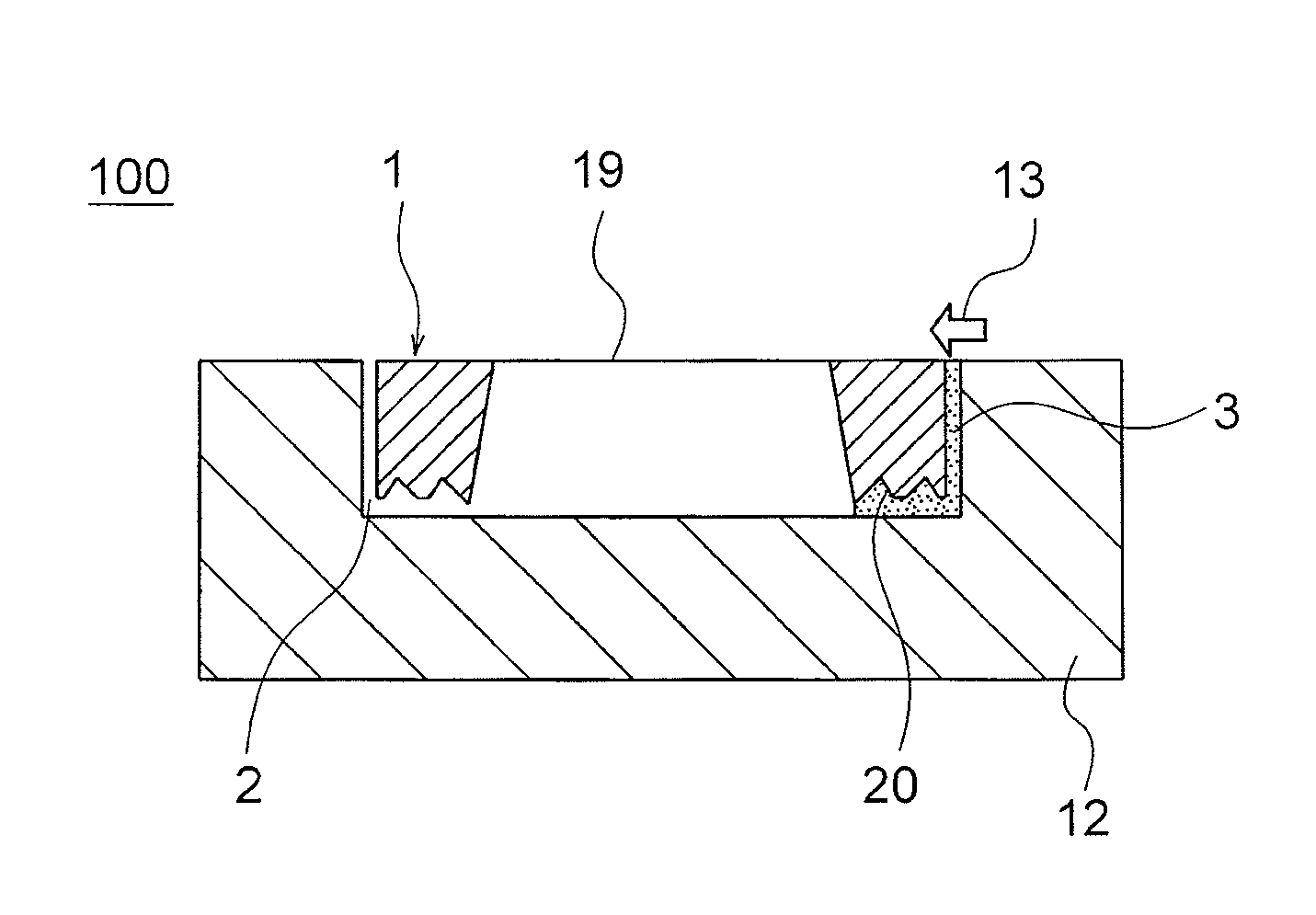
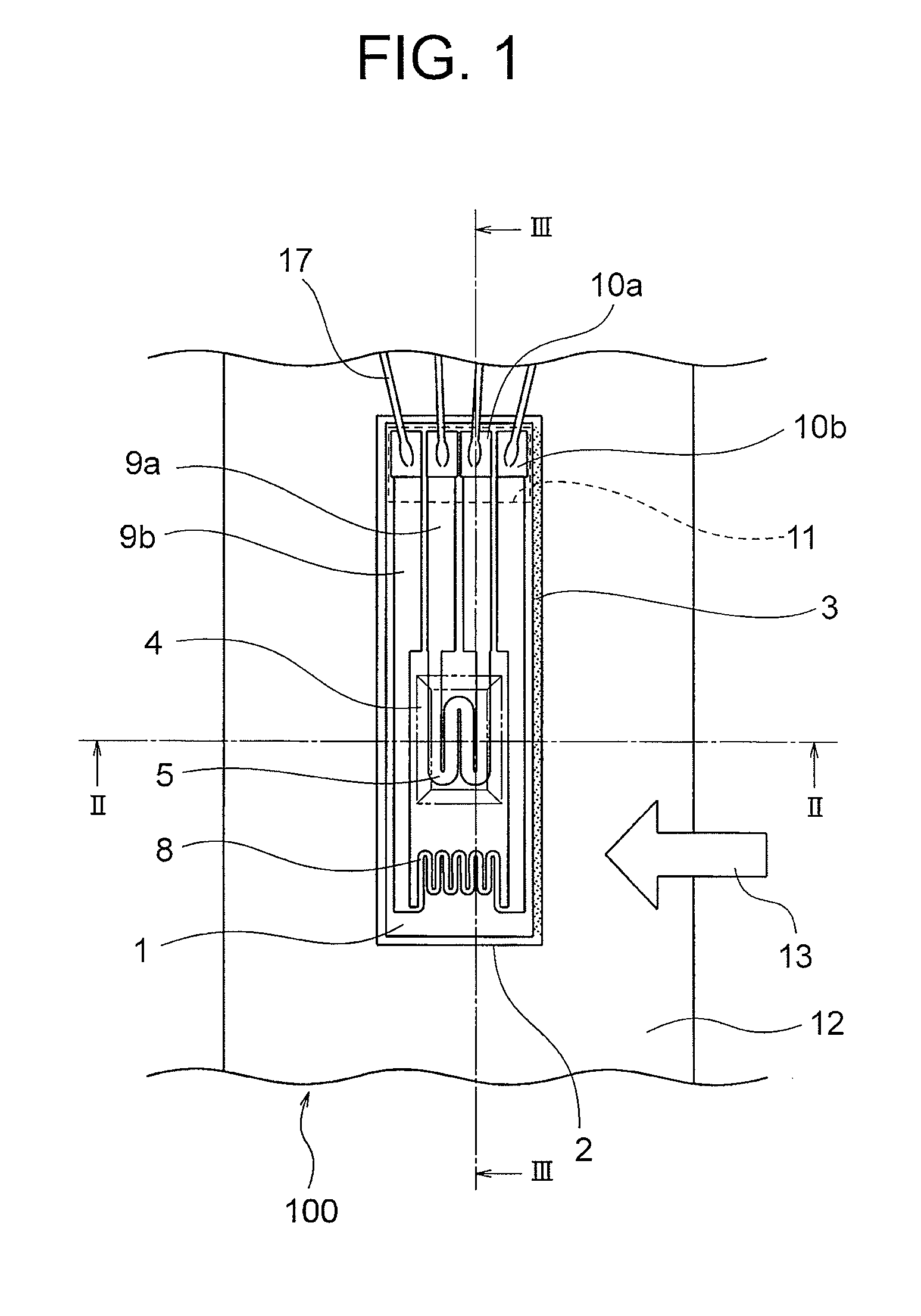
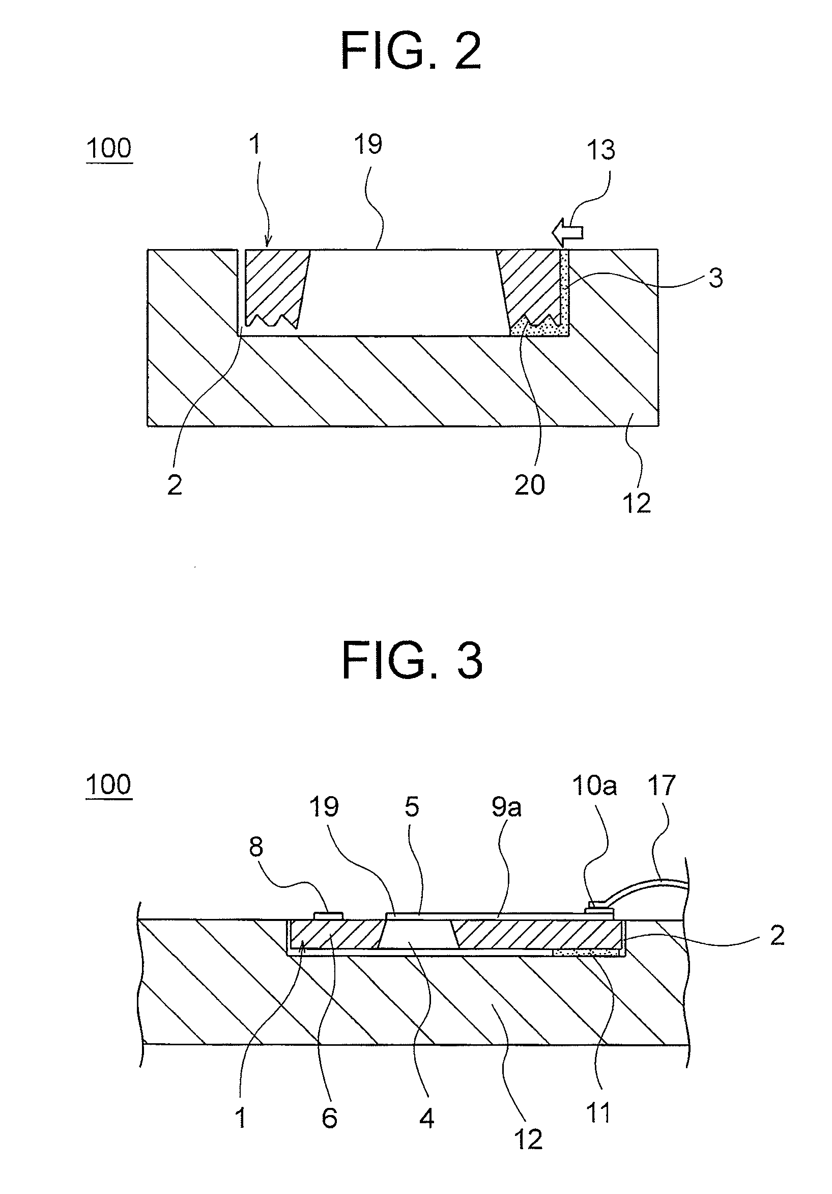
[0031]Referring to FIGS. 1 to 10C, a structure of a sensor element 1 and a manufacturing process therefor according to a first embodiment of the present invention are described below. FIG. 1 is a plan view of a flow rate detection device 100 according to the first embodiment of the present invention, and FIGS. 2 and 3 illustrate cross-sectional structures thereof cut along the lines II-II and III-III of FIG. 1, respectively.

[0032]The flow rate detection device 100 according to the first embodiment includes the sensor element 1 and a support 12. The sensor element 1 includes a cavity 4, which is formed in a rear surface of a plate-shaped semiconductor silicon substrate 6 by removing part of the plate-shaped semiconductor silicon substrate 6, and a thin film portion 19 (heating element 5), which is disposed over the cavity 4 and includes a detecting element. The support 12 includes a fitting portion 2 into which the sensor element 1 is to be disposed and fitted, and is installed ...

second embodiment

[0051

[0052]Referring to FIGS. 11 to 13, a second embodiment of the present invention is described. The second embodiment provides an uneven structure in which the square pyramid recesses as the texture of the sensor element 1 according to the first embodiment are arrayed in a regular manner (hereinafter, also referred to as inverted pyramid texture).

[0053]In the following, a manufacturing process therefor is described. The same manufacturing process for the sensor element 1 as in the first embodiment is applicable until the cavity 4 is formed in the plate-shaped silicon substrate 6 as illustrated in FIG. 5A. In other words, as illustrated in FIG. 5B, the cavity 4 is formed along the sides of the heating element 5 similarly to the first embodiment.

[0054]In the second embodiment, after the formation of the cavity 4 of FIG. 5B, a grid-like oxide film pattern is formed on a rear surface of the silicon wafer by photolithography process or etching using a grid-like photomask pattern 122 h...

third embodiment

[0057

[0058]Described as a third embodiment of the present invention are two modes of forming a texture by a dry process, which is used in the semiconductor technology. FIG. 14 is a plan view of a flow rate detection device to be obtained in the third embodiment of the present invention, and FIGS. 15A to 15E and 16A to 16E each illustrate a forming process therefor in cross section viewed in the line A-A of FIG. 14. The flow rate detection device to be obtained in the third embodiment has a structure obtained by cutting the flow rate detection devices provided on the silicon substrate by a cutter or the like to separate one flow rate detection device to another. On the front side of the flow rate detection device, the support film 15 and the protective film 14, which are formed of an insulating material, and the thermosensitive resistor films are formed in a laminated structure. In the rear surface of the flow rate detection device, the cavity 4 having an opening is disposed. The flo...


PUM


Abstract

The flow rate detection device includes a sensor element and a support. The sensor element includes: a cavity which is formed in a rear surface of a plate-shaped semiconductor silicon substrate by removing part of the plate-shaped semiconductor silicon substrate; and a thin film portion which is disposed over the cavity and includes a detecting element. The support includes a fitting portion into which the sensor element is to be disposed. The sensor element is supported to the fitting portion by an adhesive in a floating manner. A gap formed between the sensor element and the fitting portion is filled with an anti-undercurrent material. The sensor element has a texture including protrusions and depressions formed on a surface opposed to the fitting portion, and the anti-undercurrent material is brought into contact with the texture.

Description

BACKGROUND OF THE INVENTION[0001]1. Field of the Invention[0002]The present invention relates to a flow rate detection device for measuring the volume of air.[0003]2. Description of the Related Art[0004]Until now, as a device for measuring the volume of air in an internal combustion engine, for example, there has been known a flow rate detection device employing an inflow temperature-dependent resistor. The flow rate detection device is provided with a sensor element including a heating element and an intake air temperature detector. The sensor element is kept under control so that a temperature of the heating element is higher than a temperature detected by the intake air temperature detector by a given amount, so as to detect a voltage corresponding to an amount of heat that the heating element dissipates into a fluid, to thereby detect a flow rate of the fluid finally.[0005]Japanese Patent Application Laid-open No. 09-026343 discloses an example of a support structure for the sen...

Claims


Application Information

Patent Timeline
Patent Type & Authority Patents(United States)
IPC IPC(8): G01F1/68
CPCG01F1/6842G01F15/14G01F1/6845
Inventor NAKANISHI, TAIKIINOUE, HIROMOTOKAWAMA, YOSHITATSU
Owner MITSUBISHI ELECTRIC CORP
Why Eureka
Try Eureka