Method for controlling a hybrid traction assembly and hybrid vehicle controlled according to such a method

a hybrid traction and hybrid vehicle technology, applied in the direction of automatic control systems, process and machine control, instruments, etc., can solve the problems of shortening the service life of storage devices, prior art controlling methods which are common to many vehicles, and not being desirable from many standpoints

Active Publication Date: 2014-05-13
VOLVO TRUCK CORP
View PDF13 Cites 9 Cited by
  • Summary
  • Abstract
  • Description
  • Claims
  • Application Information

AI Technical Summary

Benefits of technology

[0014]This prior art controlling method makes it possible to somewhat downsize the internal combustion engine. Indeed, the electric traction motor can boost the total hybrid traction power and thus compensate for the power loss resulting from this downsizing.
[0016]First of all, the prior art controlling method induces a big difference in the way the vehicle behaves during the two main phases, i.e. during the high rate depleting phase and the sustaining phase. Indeed, the performance, the noise and the emissions of the vehicle will be dramatically different between those two main phases.

Problems solved by technology

This prior art controlling method which is common to many vehicles is not desirable from many standpoints.
First of all, the prior art controlling method induces a big difference in the way the vehicle behaves during the two main phases, i.e. during the high rate depleting phase and the sustaining phase.
Besides, controlling a battery set with a short but strong depleting phase followed by a long sustaining phase may shorten the service life of the storage device.

Method used


Image

  • Method for controlling a hybrid traction assembly and hybrid vehicle controlled according to such a method
  • Method for controlling a hybrid traction assembly and hybrid vehicle controlled according to such a method
  • Method for controlling a hybrid traction assembly and hybrid vehicle controlled according to such a method

Examples


first embodiment

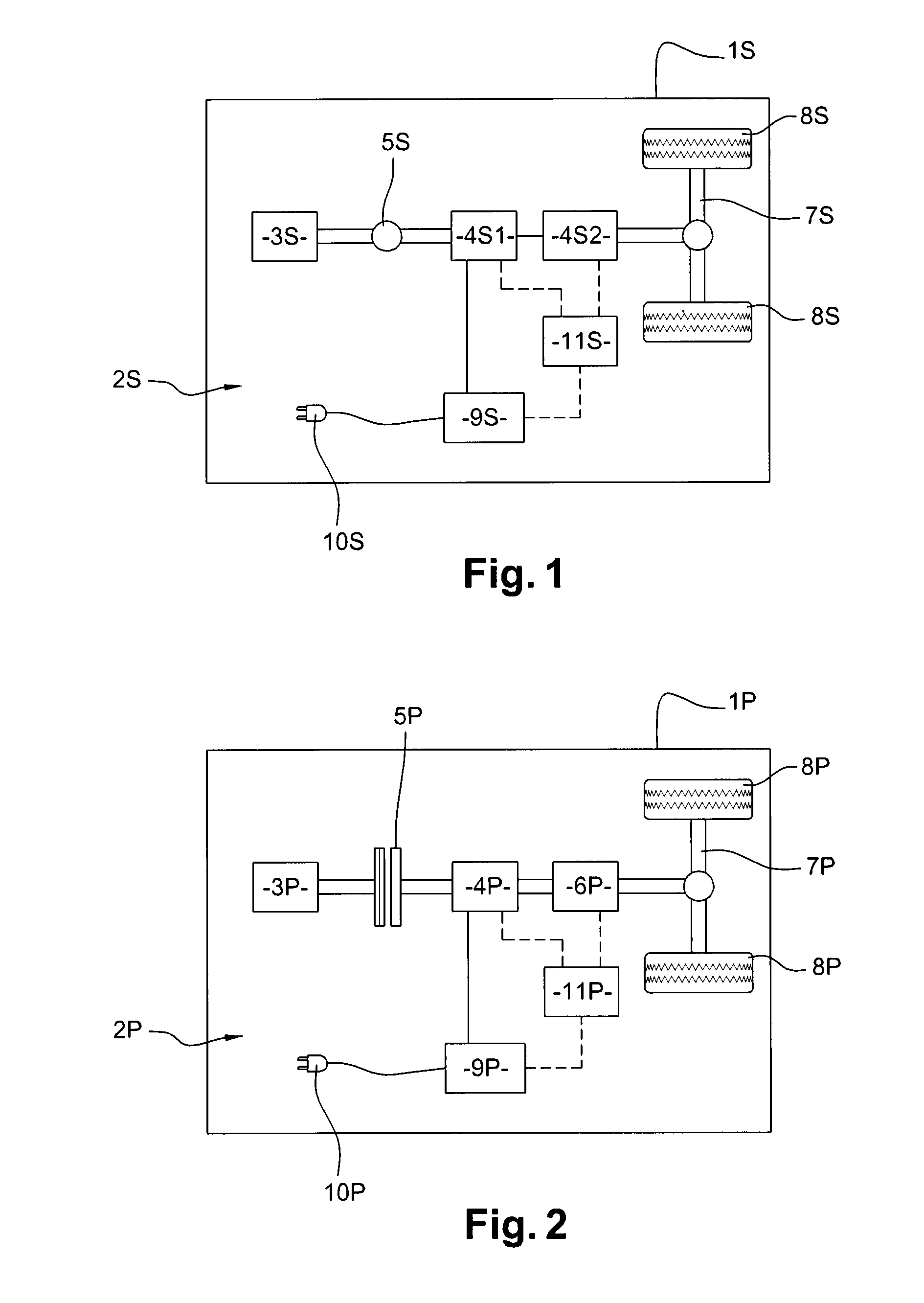
[0037]FIG. 1 depicts a hybrid vehicle 1 S according to the present invention, for instance an industrial vehicle, which has a hybrid traction assembly 2S. Hybrid vehicle 1 is of the series hybrid type. Hybrid traction assembly 2S comprises an internal combustion engine 3S and two electric machines 4S1, 4S2. The internal combustion engine 3S is coupled to one of the electric machine 4S1 which operates mainly as a generator to produce electrical current. The second electric machine 4S2 mostly works as an electric traction motor, etc.

[0038]Advantageously, the electric machines 4S1, 4S2 can be reversible machines. They can for example be brushless direct current motors with permanent magnets, alternate current induction motors.

[0039]The second electric machine 4S2 can work as an electric generator, for generating electric regenerative energy when the hybrid vehicle 1 S slows down or brakes. When any decelerating command is given, e.g. when the brake pedal is depressed, this electric mac...

second embodiment

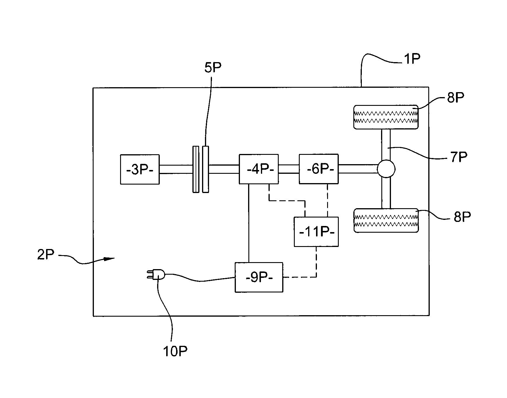
[0043]FIG. 2 depicts a hybrid vehicle 1 P according to the present invention, for instance an industrial vehicle, which has a hybrid traction assembly 2P. Most of the parts of hybrid vehicle 1 P have structures and / or functions that are quite similar to the structures and / or functions of the corresponding parts of hybrid vehicle 1 S depicted on FIG. 1. Hence, the afore-stated description of hybrid vehicle 1 S given in relation to FIG. 1 can be transposed to hybrid vehicle 1 P of FIG. 2, except for the hereafter-stated differences.

[0044]In most cases, the reference sign of a part of hybrid vehicle 1 P can be derived, by replacing suffix letter S by suffix letter P, from the reference sign of the part of hybrid vehicle 1 S that has the corresponding structure and / or function. One can thus define:

[0045]hybrid vehicle 1 P;

[0046]a hybrid traction assembly 2P;

[0047]an internal combustion engine 3P;

[0048]an electric machine 4P;

[0049]a transmission 6P:

[0050]wheel shafts 7P;

[0051]driving whe...


PUM


Abstract

A method for controlling a hybrid traction assembly includes an initial depleting phase which begins at the beginning of the vehicle mission and where the hybrid traction assembly is controlled to cause depletion of the storage device at a high first mean depletion rate, at least one sustaining phase where the hybrid traction assembly is controlled so that the state of charge is maintained in a predetermined sustaining range. The method further includes a second depleting phase which extends between the initial depleting phase and the sustaining phase, wherein the hybrid traction assembly is controlled to cause depletion of the storage device at a second mean depletion rate, the second mean depletion rate being lower than the first mean depletion rate.

Description

BACKGROUND AND SUMMARY[0001]The present invention relates to a method for controlling a hybrid traction assembly of a vehicle. Besides, the present invention relates to an automotive vehicle, especially an industrial plug-in hybrid vehicle, which can be controlled according to such a method.[0002]A prior art hybrid vehicle usually has a hybrid traction assembly which can comprise an internal combustion engine, at least one electric reversible machine for performing traction of the hybrid vehicle and for generating electric regenerative energy when the vehicle slows down, and an electric energy storage device comprising, if it is of the co-called “plug-in” type, a connector for connection to the grid. Sometimes, instead of a reversible machine, a prior art hybrid vehicle can comprise an electric motor and an electric generator.[0003]In a parallel type hybrid, both the internal combustion engine and the electric machine may provide torque to the driveline of the vehicle. The electric ...

Claims


Application Information

Patent Timeline
Patent Type & Authority Patents(United States)
IPC IPC(8): G06F7/00B60W20/00B60W10/08B60W10/06B60L50/16
CPCY10S903/93B60W30/18B60W10/06Y02T10/6269B60W10/26Y02T10/6286B60W10/08B60W20/106B60W20/104B60W20/102B60W20/00B60W2550/402B60W2600/00Y02T10/7077B60W2510/244Y10T477/23B60W20/13B60W20/11B60W20/12B60W2556/50Y02T10/62B60W2556/00Y02T10/7072
Inventor JUSTIN, THOMASMILLET, MICHAEL
Owner VOLVO TRUCK CORP
Why Eureka
Try Eureka