Resonant flow sensor and uses and production methods for the same

a flow state sensor and resonance technology, applied in the direction of liquid/fluent solid measurement, manufacturing tools, instruments, etc., can solve the problems of high sampling rate, laborious amplification, and large configuration complexity of prior-art flow state sensors

Inactive Publication Date: 2014-05-27
AIRBUS OPERATIONS LTD +1
View PDF6 Cites 5 Cited by
  • Summary
  • Abstract
  • Description
  • Claims
  • Application Information

AI Technical Summary

Benefits of technology

[0011]The object of the invention is to provide a flow state sensor of a simple construction and a simple flow measuring method for detecting flow states at a body impinged on by a flow.

Problems solved by technology

All of those prior-art flow state sensors share the disadvantage of having a relatively elaborate configuration.
A further disadvantage is that all of those sensors provide an analogue sensor signal, which requires laborious amplification of the signal, a high sampling rate and therefore extensive data collection and data evaluation in order for the decision to be made between “laminar” or “non-laminar” at the geometrical location of an individual sensor element.
Hot-wire sensors and hot-film sensors moreover have a high energy consumption and require complex electronics and data evaluation.
A comparatively large amount of power is required to operate such sensors.
A first problem with U.S. Pat. No. 5,272,915 is that a bandpass filter is required in order to sense the presence of energy in the 50-80 Hz passband.
A second problem with U.S. Pat. No. 5,272,915 is that it cannot reliably detect a fully turbulent flow state which typically has a significant amount of energy with a frequency greater than 1 kHz.
In addition, they are not sufficiently sensitive for highly dynamic measurements, for example for establishing a transition at high oncoming flow velocities.
Robust dynamic pressure sensors, which also have already been used in the field of flow measurement, do not in most cases have the required sensitivity to be used for transition measurements.

Method used


Image

  • Resonant flow sensor and uses and production methods for the same
  • Resonant flow sensor and uses and production methods for the same
  • Resonant flow sensor and uses and production methods for the same

Examples


first embodiment

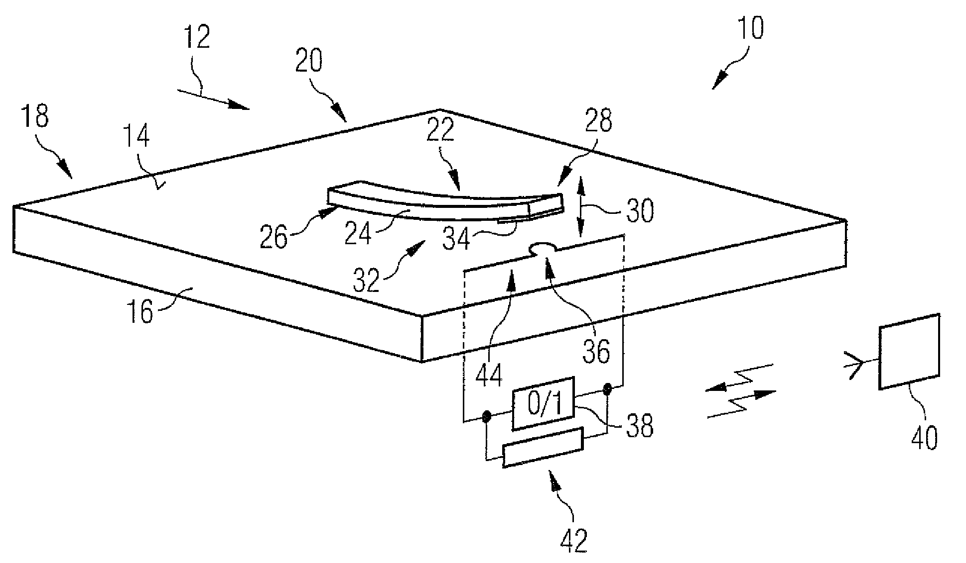
[0047]In the case of the flow state sensor 10 illustrated in FIG. 1, the oscillation element 22 is mounted on the flow-impinged surface 14 of the body 16 around which the flow passes. The oscillation element 22 can thereby interface with the flow 12 in the optimum manner.

[0048]In that case, however, there is also the possibility that the oscillation element 22 will affect the flow 12 downstream of the oscillation element 22.

[0049]To avoid or reduce such an effect, an actuable damping unit 42 is provided by means of which the oscillation element is damped in its oscillatory movement or held completely fixed by external actuation. In one embodiment illustrated herein, the damping unit 42 utilizes the above-mentioned elements 34, 36 of the energy generating device 32. For example, by applying a voltage to the conductor 36, a magnetic field is produced which acts on the magnetic layer for damping or fixing purposes. By means of the damping unit 42 it is possible to prevent potential inf...

second embodiment

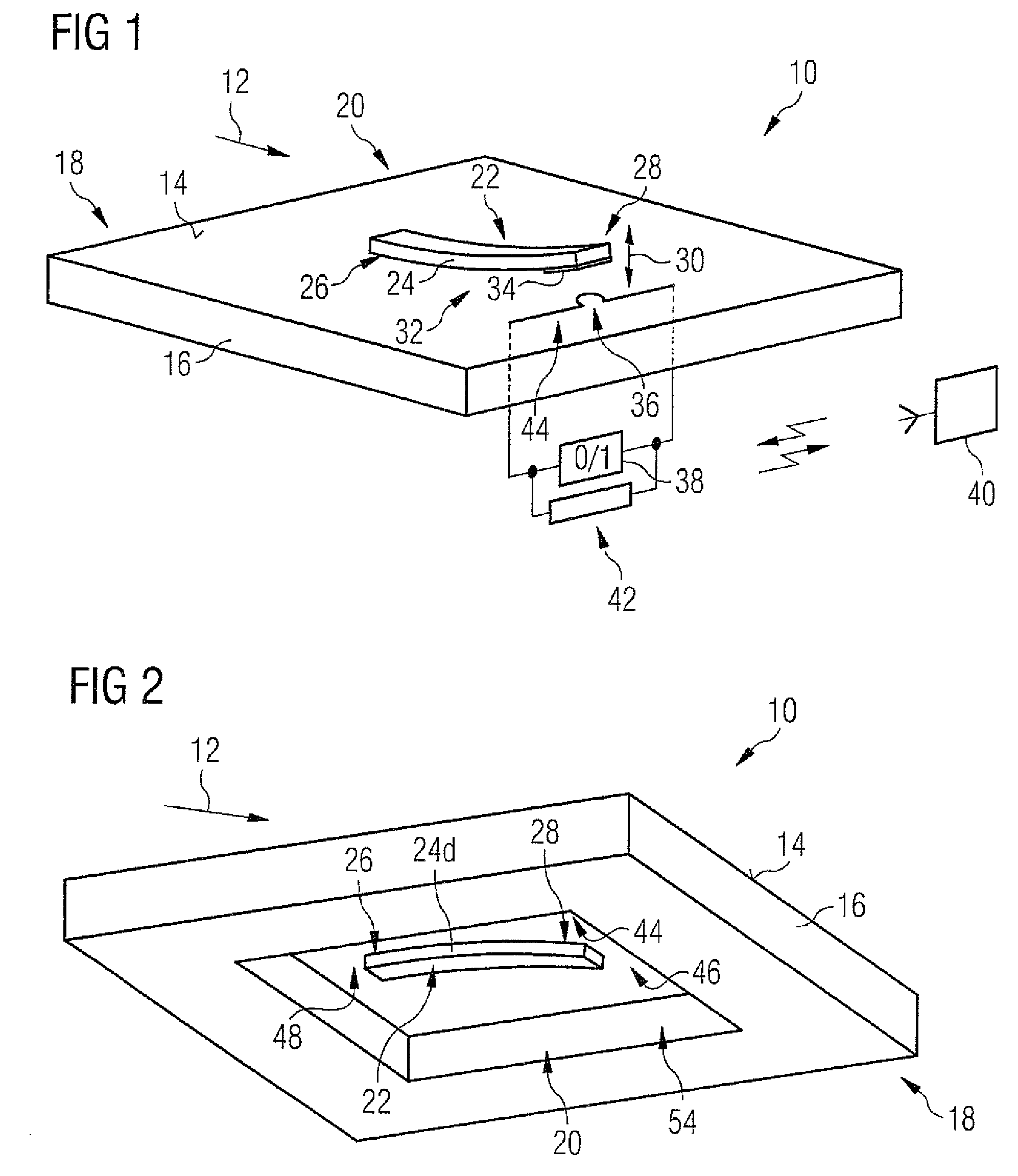
[0051]In FIG. 2, the flow state sensor 10 is illustrated. The same reference numerals are used for corresponding parts. To provide better protection for the flow state sensor 10 against external environmental conditions, a resonant sensor element, especially the at least one oscillation element 22, is disposed on that side 46 of a diaphragm 48 which faces away from the flow. The oscillation element 22 is in this case configured as a multilayer strip 24 consisting of a plurality of layers that have been appropriately configured during production to set the natural frequency.

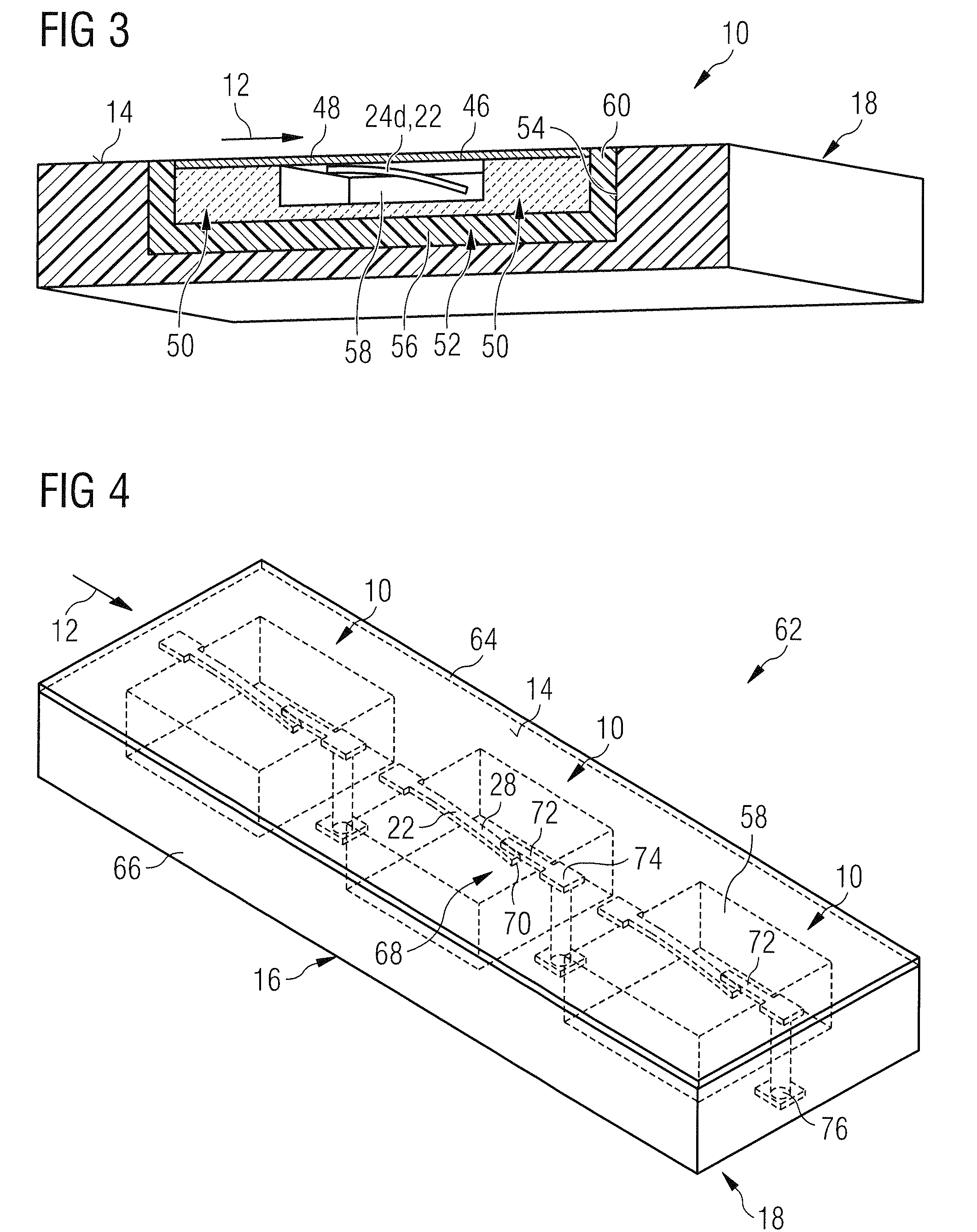
[0052]FIG. 3 shows the flow state sensor 10 in accordance with the second embodiment, built into the component 18. The flow state sensor 10 has a housing 50 which as regards oscillation is decoupled from the component 18 by means of a damping device 52. The damping device 52 together with the housing 50 is built into a cavity 54 in the component 18 and has a damping layer 56 and a damping material 60 that effectiv...


PUM

PropertyMeasurementUnit
resonant frequencyaaaaaaaaaa
lengthaaaaaaaaaa

Abstract

The invention relates to a flow state sensor (10) for detecting a flow state at a body (16) that may be impinged on by a flow (12). A flow state sensor (10) that is of a simple construction and that is simple to evaluate is characterized in accordance with the invention by at least one frequency detecting device (20) for detecting at least one predefined frequency characteristic of the flow state. The frequency detecting device (20) has at least one oscillation element (22; 22a, 22b, 22c) excitable to resonant oscillatory movement (30) by a flow (12) and having a resonant frequency or natural frequency adapted to the predefined frequency characteristic, especially corresponding to the predefined frequency characteristic. Uses of the flow state sensor (10) in a flow measuring device (62) and in a flow measuring method, and an advantageous production method for the flow state sensor (10) are also proposed.

Description

[0001]This application is the U.S. national phase of International Application No. PCT / GB2009 / 050930 filed 27 Jul. 2009, which designated the U.S. and claims priority to DE Application No. 10 2008 035 423.6 filed 30 Jul. 2008, the entire contents of each of which are hereby incorporated by reference.FIELD OF THE INVENTION[0002]The invention relates to a flow state sensor for detecting a flow state at a body that may be impinged on by a flow. In addition, the invention relates to a flow measuring device having a plurality of such flow state sensors, to a production method for the flow state sensor and the flow measuring device, and to a flow measuring method which may be carried out with such a flow state sensor.BACKGROUND OF THE INVENTION[0003]Studies of the flow state are important for the planning and design of aircraft and especially of wing profiles. As described in detail by M. Gad-el-Hak in “Flow Control: Passive, Active and Reactive Flow Management”, Cambridge University Pres...

Claims


Application Information

Patent Timeline
Patent Type & Authority Patents(United States)
IPC IPC(8): G01M9/00
CPCG01H13/00G01P5/01Y10T29/49826
Inventor WOOD, NORMANBAUER, KARINRIEDL, XAVERWAGNER, ROLAND
Owner AIRBUS OPERATIONS LTD
Why Eureka
Try Eureka