Optical communication module and optical communication connector

a technology which is applied in the field of optical communication module and optical communication connector, can solve the problems of increasing the size of the module including a circuit part (device), the inability of the single-core bidirectional optical communication module to be assembled into the optical connector, and the increase in the size of the single-core bidirectional optical communication connector. , to achieve the effect of simplifying the positioning process for mounting the optical filter, and reducing the size of the modul

Active Publication Date: 2014-05-27
YAZAKI CORP
View PDF23 Cites 17 Cited by
  • Summary
  • Abstract
  • Description
  • Claims
  • Application Information

AI Technical Summary

Benefits of technology

[0033]According to the first embodiment of the invention, it is not necessary to greatly change the structure of the optical connector housing which is an assembly destination of the single-core bidirectional optical communication module, compared with the structure of the past optical connector housing. According to the invention, it is possible to reduce the size of the module.
[0034]According to the second embodiment of the invention, it is possible to simplify the positioning process for mounting the optical filter and to achieve the decrease in size of the module, by employing the structure of the optical path changing component. According to the invention, since the optical filter is interposed between the optical filter mounting portion of the optical path changing component and the optical filter fixing component, it is possible to loosen the stress due to the difference in thermal expansion coefficient between the optical filter and the optical path changing component at the time of variation in temperature, thereby preventing the destruction or peeling of the optical filter.
[0035]According to the third embodiment of the invention, by integrating the sleeve with the optical path changing component, it is possible to simplify the structure of the optical connector housing which is an assembly destination of the single-core bidirectional optical communication module. According to the invention, it is possible to improve the optical coupling state.
[0036]According to the fourth embodiment of the invention, by injecting the resin into the space in which the optical elements are present through the through-hole, it is possible to cover various components or bonding wires in the optical transceiver circuit unit with the protective resin without being exposed to the space, thereby protecting the components or bonding wires. According to the invention, it is possible to prevent the deterioration or detachment of components and the peeling of the bonding wires due to the influence of humidity or the vibration in use or the like. In addition, according to the invention, since the protective resin is injected into the space in which the optical elements are present in the state where the optical path changing component and the optical transceiver circuit unit are fixed, it is possible to gather the protective resin in the space and thus to make planar the surface of the protective resin covering the optical elements. Accordingly, it is possible to facilitate the optical design including the protective resin. By closing the through-hole, it is possible to prevent the intrusion of particles or the like through the through-hole.
[0037]According to the fifth embodiment of the invention, it is possible to provide a single-core bidirectional optical communication connector which can decrease in size without greatly changing the structure of the past optical connector housing.

Problems solved by technology

The single-core bidirectional optical communication module disclosed in PTL 2 has a problem in that the size of the module including a circuit part (device) increases (whereby the single-core bidirectional optical communication connector also increases in size), since the light-emitting element and the light-receiving element are disposed to be orthogonal to each other.
Since the light-emitting element and the light-receiving element are disposed to be orthogonal to each other, there is a problem in that the single-core bidirectional optical communication module cannot be assembled into the optical connector housing having the structure according to the related art.
Since it is also necessary to guarantee an assembly space for the dedicated component, there is also a problem in that the size of the module increases as described above.
Accordingly, there is also a problem in that the manufacturing difficulty increases.
The single-core bidirectional optical communication module disclosed in PTL 3 has a problem in that it cannot be assembled into the optical connector housing having the structure according to the related art.
Since the optical filter is bonded to the optical path changing component, there is also a problem in that the optical filter may be destroyed due to the difference in the thermal expansion coefficient between the materials thereof.

Method used


Image

  • Optical communication module and optical communication connector
  • Optical communication module and optical communication connector
  • Optical communication module and optical communication connector

Examples


first embodiment

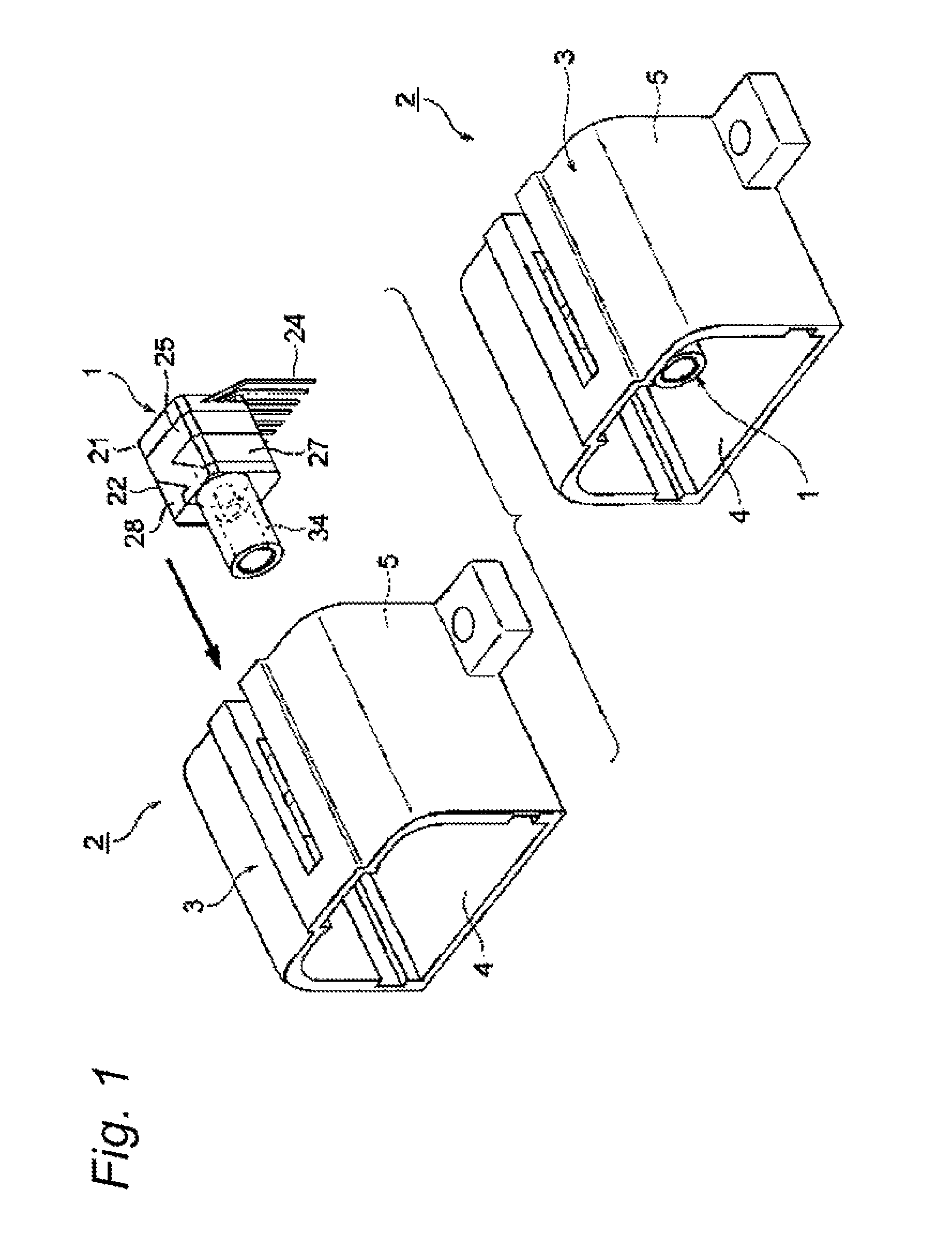
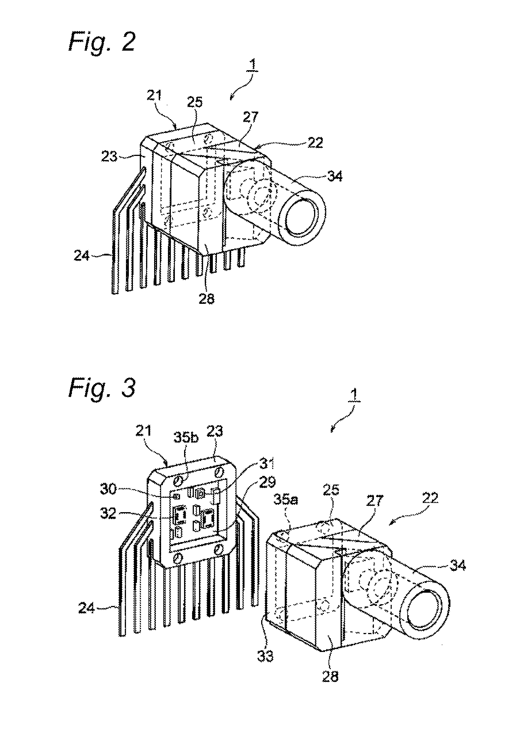
[0059]Hereinafter, a first embodiment of the invention will be described with reference to the accompanying drawings. FIG. 1 is a diagram illustrating a single-core bidirectional optical communication module and a single-core bidirectional optical communication connector according to a first embodiment of the invention. FIG. 2 is a perspective view of the single-core bidirectional optical communication module, FIG. 3 is a perspective view of the optical transceiver circuit unit and an optical unit, FIGS. 4 and 5 are exploded perspective views of the single-core bidirectional optical communication module, FIG. 6 is a perspective view of the optical path changing component, FIG. 7 is a sectional view of the optical unit in a state where an optical filter mounted thereon, and FIGS. 8 to 10 are sectional views of a module illustrating an optical path.

[0060]In FIG. 1, reference numeral 1 represents a single-core bidirectional optical communication module according to the invention. Refer...

second embodiment

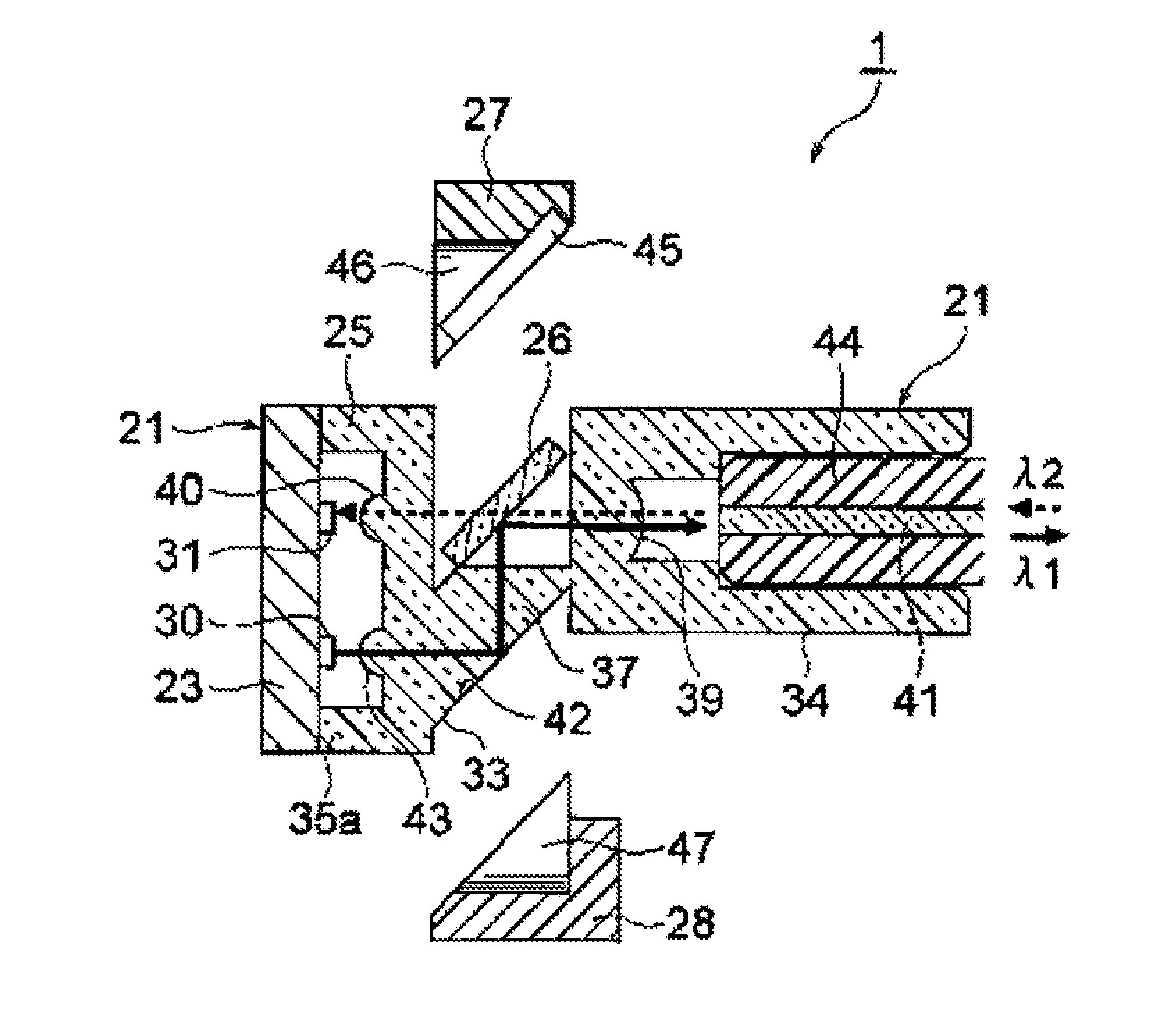
[0088]A second embodiment of the invention will be described below with reference to the accompanying drawings. FIG. 11 is a sectional view of a module illustrating the optical paths for transmission (λ1) and reception (λ2). The same constituent elements as the first embodiment are referenced by the same reference numerals and detailed description thereof is not repeated.

[0089]As shown in FIG. 11, the arrangement of the light-emitting element 30 and the light-receiving element 31 in the second embodiment is opposite to the first embodiment (the positions are exchanged). The transmission light from the light-emitting element 30 is transmitted by the optical filter 26 and is then coupled to the optical fiber cable 41. On the other hand, the reception light from the optical fiber cable 41 is reflected and bent by 90° by the optical filter 26 and is then bent by 90° again by the 45° prism face 42. Then the reception light is coupled to the light-receiving element 31 (the optical filter ...

third embodiment

[0090]A third embodiment of the invention will be described below with reference to the accompanying drawings. FIG. 12 is a sectional view of a single-core bidirectional optical communication module. The same constituent elements as the first embodiment are referenced by the same reference numerals and detailed description thereof is not repeated.

[0091]In FIG. 12, the single-core bidirectional optical communication module 51 according to the third embodiment does not include the optical face protecting component 28 (see FIG. 2) included in the first embodiment but has a mirror 52 disposed at the position of the 45° prism face 42. The mirror 52 is formed by “electroless plating” or “deposition of a conductive multi-layered film”. The third embodiment is an example which is designed to make the optical face protecting component 28 unnecessary, and thus the optical filter 26 may be mounted to bend the optical path by 90°.


PUM


Abstract

A single-core bidirectional optical communication module and a single-core bidirectional optical communication connector are provided which can decrease in size without greatly changing the structure of the past optical connector housing. An optical communication module 1 includes an optical transceiver circuit unit 21 in which a light-emitting element and a light-receiving element are arranged in parallel and an optical path changing component 25 having a structure in which the attachment and detachment direction of an optical fiber cable is perpendicular to the optical transceiver circuit unit 21. An optical communication connector 2 includes a single-core bidirectional optical communication module 1 and an optical connector housing3 that houses the single-core bidirectional optical communication module 1 so that the optical axis of the optical fiber cable is perpendicular to the optical transceiver circuit unit 21.

Description

TECHNICAL FIELD[0001]The present invention is related to an optical communication module and an optical communication connector. Particularly, the present invention relates to a single-core bidirectional optical communication module used to perform bidirectional optical communication using a single optical fiber cable and a single-core bidirectional optical communication connector (optical connector) having the single-core bidirectional optical communication module.BACKGROUND ART[0002]Optical communication connectors having a structure in which a light-emitting element and a light-receiving element are optically connected to two optical fiber cables have been widely known. Single-core directional optical communication connectors having a structure in which a light-emitting element and a light-receiving element are optically connected to a single optical fiber cable have also been known (for example, see PTL 1).[0003]The single-core bidirectional optical communication connector discl...

Claims


Application Information

Patent Timeline
Patent Type & Authority Patents(United States)
IPC IPC(8): G02B6/42G02B6/26G02B6/36
CPCG02B6/4214G02B6/4246G02B6/4292
Inventor KAWAI, HIROKI
Owner YAZAKI CORP
Why Eureka
Try Eureka