
Integrated cooling, heating, and power systems

a technology of integrated cooling and power systems, applied in the field of integrated cooling, heat and power systems, can solve the problems of low overall thermal/electric efficiency of existing micro-cchp systems, large and constant electric power, and large so as to reduce the footprint and size of cchp systems and increase the system performance. , the effect of increasing the system performan

Active Publication Date: 2014-06-03
UNIV OF NEW ORLEANS RES TECH FOUND
View PDF24 Cites 5 Cited by
  • Summary
  • Abstract
  • Description
  • Claims
  • Application Information

AI Technical Summary

Benefits of technology

[0006]This invention addresses this need by providing, amongst other things, a method of integrating a gas turbine, an absorption chiller, and a gas turbine inlet chiller into a compact module. This invention further provides a method for producing a large and constant electric power by using a gas turbine inlet cooling technology. Also, this invention provides a method of integrating the heat recovery unit into a generator of the absorption chiller system to eliminate the stand-alone heat recovery system, as well as a method of removing the cooling tower by incorporating the condenser cooling system in the absorber of the absorption chiller. This will significantly reduce the footprint and size of the CCHP system, increase the system performance, and make it easy to transport, install, and control.

Problems solved by technology

However, the known systems all have their drawbacks.
For residential or small business applications, the current practice is too complicated, bulky, expensive, and intimidating.
Furthermore, the overall thermal / electric efficiency of existing micro-CCHP systems are generally below 70% and hover at 65% due to the small sizes of each component and the additional irreversibility generated between individual commercial units.

Method used


Image

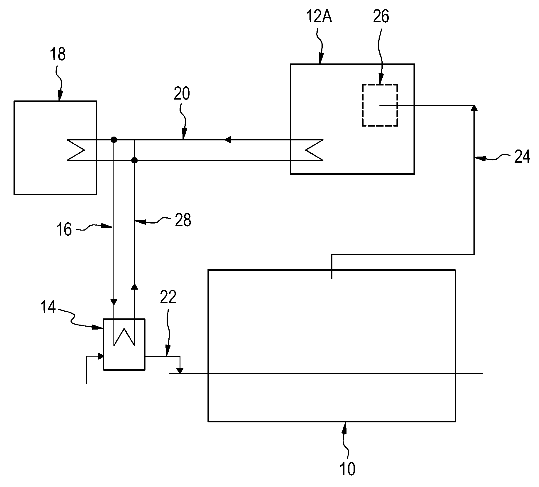
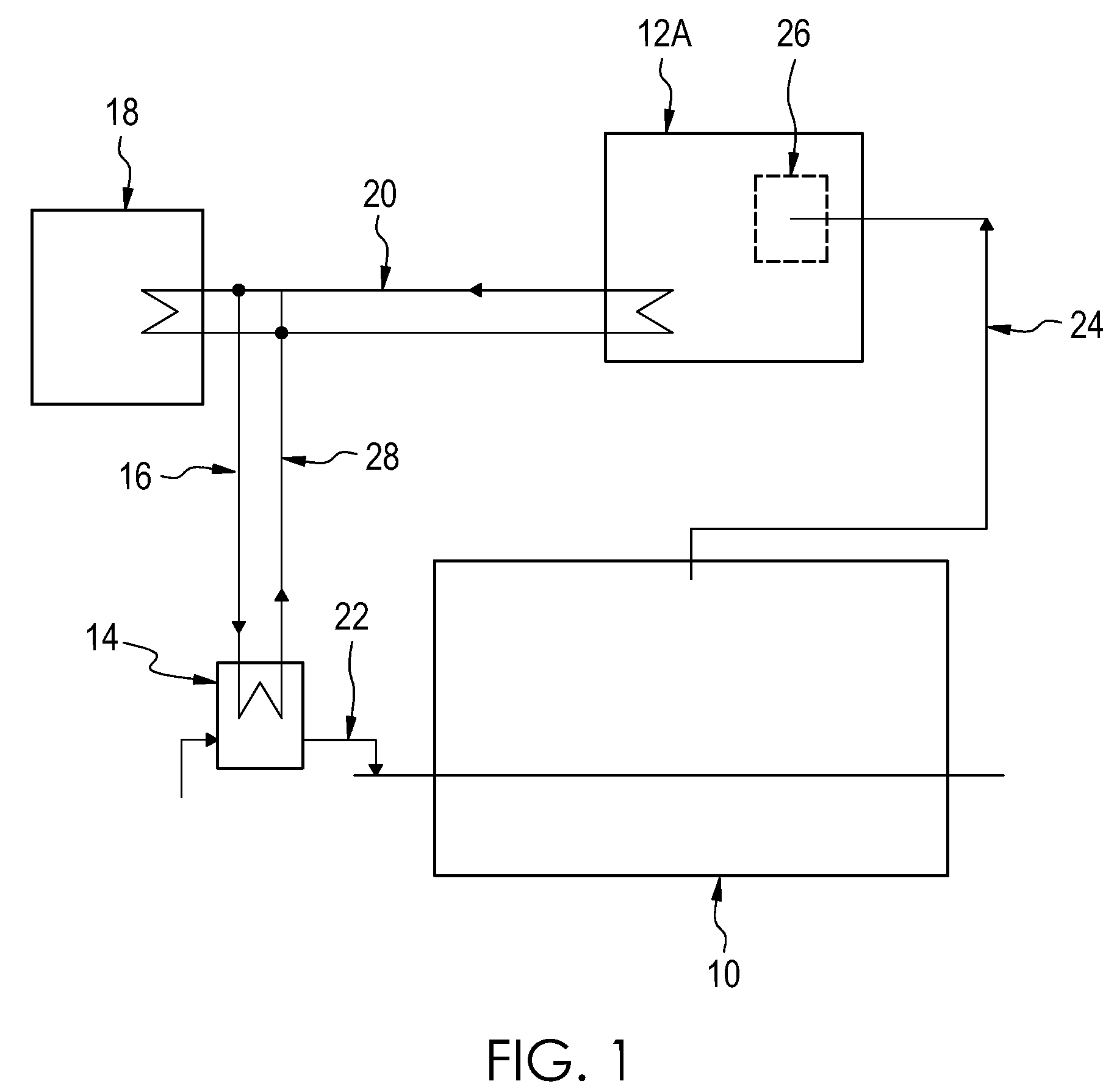
  • Integrated cooling, heating, and power systems
  • Integrated cooling, heating, and power systems
  • Integrated cooling, heating, and power systems

Examples


first embodiment

[0023]As demonstrated in certain embodiments of the present invention, a single-effect or multiple-effect absorption chiller is a better candidate to provide inlet air cooling than existing technologies, especially when the requirement for hot water diminishes in summer months. Also, during the summer, excess heat can be effectively utilized as an energy source for the single-effect or multiple-effect absorption chiller. Therefore, as shown in FIG. 1, this invention integrates an absorption chiller system with the micro-gas turbine to provide turbine inlet air-cooling, boost fuel-electricity efficiency, and power output in summer.

[0024]A single-effect or multiple-effect absorption chiller employed as part of the system of the first embodiment of this invention provides space cooling as well as cooling for the turbine inlet air. Cooling of the turbine inlet air in this manner allows the air to be cooled down to at least the ISO condition (59° F. and 60% relative humidity) during the ...

second embodiment

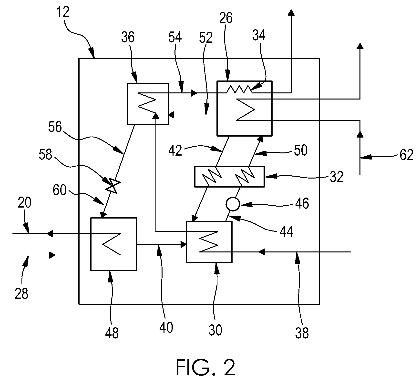
[0027]this invention depicted in FIG. 2 eliminates the need for a stand-alone HRU and a cooling tower, which are necessary in known systems, by adding a heat exchanger to the generator of the single-effect absorption chiller and by utilizing a feed of water from a source as a cooling system in the absorber and in the condenser of the absorption chiller.

[0028]In known single-effect absorption chillers, the generator serves as a liquid-vapor separator and usually occupies a relatively large volume. However, in the second embodiment of the present invention, a heat exchanger component of the generator allows water to pass through the generator in a separate path and be heated by turbine exhaust gas, as shown in FIG. 2. This design can remove the current HRU used in known systems and take advantage of the generator's volume for heating water. This integration will significantly reduce the space, cost, and system irreversibility.

[0029]Also, by using the second embodiment of the present i...

third embodiment

[0030]In known multiple-effect absorption chillers, the terminal generator serves as a liquid-vapor separator and usually occupies a relatively large volume. However, in the present invention, a heat exchanger component of the terminal generator allows water to pass through the terminal generator in a separate path and be heated by turbine exhaust gas, as shown in FIG. 3. This design can remove the current HRU used in known systems and take advantage of the terminal generator's volume for heating water. This integration will significantly reduce the space, cost, and system irreversibility.

[0031]Also, by using the third embodiment of the present invention, as demonstrated in FIG. 3, the cooling tower employed with most multiple-effect absorption chillers in known systems can be removed by using a feed of water from a source through the absorber and then by redirecting the feed of water from the absorber to the initial condenser, so energy released from the initial condenser can be ef...


PUM


Abstract

One exemplary embodiment of this invention provides a single-effect absorption chiller including an absorber operatively connected to a solution heat exchanger and a generator, and a condenser in fluid communication with the absorber, wherein the absorber is sized and configured to receive a feed of water from a source of water and to transfer heat to the feed of water and then to convey the feed of water to the condenser without further heat conditioning of the feed of water prior to its entry into the condenser, and wherein the condenser is sized and configured to receive the feed of water from the absorber and to transfer heat to the feed of water, thereby cooling the condenser without resorting to an external heat exchanger such as a conventional cooling tower.

Description

REFERENCE TO RELATED APPLICATIONS[0001]This is the National Stage of International Patent Application PCT / US2008 / 055983, filed on Mar. 6, 2008, which application claims priority from U.S. Application No. 60 / 893,567, filed Mar. 7, 2007, the disclosures of which are incorporated herein by reference.TECHNICAL FIELD[0002]This invention relates to the field of integrated cooling, heat, and power systems.BACKGROUND[0003]Various efforts have been made to provide combined cooling, heat, and power systems. However, the known systems all have their drawbacks. For example, in the range of distributed generation which is less than 200 kW, which is known in the art as “micro” or “microgeneration,” the electric power generation efficiency is relatively low. Therefore, it is valuable to consider poly-generation, for example combined heating and power (CHP), as a practice for small power or heat needs.[0004]Almost all of the current combined cooling, heating, and power (CCHP) applications have been...

Claims


Application Information

Patent Timeline
Patent Type & Authority Patents(United States)
IPC IPC(8): F25B15/00
CPCY02B30/625Y02E20/14F25B27/02F01K23/10F25B15/02Y02A30/274F02C6/18F02C7/12F25B15/00
Inventor WANG, TING
Owner UNIV OF NEW ORLEANS RES TECH FOUND
Learn More