Single terahertz wave time-waveform measuring device

a time-waveform and measuring device technology, applied in the direction of optical radiation measurement, instruments, material analysis, etc., can solve the problems of short time required for this, limiting the incidence angle of terahertz wave and probe light on the electro-optic crystal, and the waveform of the electric field amplitude of the detected pulse terahertz wave becomes inaccurate in principle, etc., to achieve short time and high time resolution

Inactive Publication Date: 2014-06-03
HAMAMATSU PHOTONICS KK
View PDF6 Cites 3 Cited by
  • Summary
  • Abstract
  • Description
  • Claims
  • Application Information

AI Technical Summary

Benefits of technology

[0020]According to the present invention, a time waveform of an electric field amplitude of a pulse terahertz wave can be measured in a short time with high time resolution.

Problems solved by technology

However, in the above-described measuring technique for information on an object to be measured, to obtain a time waveform of an electric field amplitude of a pulse terahertz wave, a number of pulsed lights are output from a light source, and for each pulse, an incidence timing of probe light on an electro-optic crystal must be set, so that the time necessary for this is long.
However, depending on various conditions (the phase matching condition, the spatial layout, and the crystal size) relating to the terahertz wave detection principle, the electro-optic crystal limits the incidence angles of the terahertz wave and probe light on the electro-optic crystal.
Further, due to oblique incidence on the electro-optic crystal, the time waveform of the electric field amplitude of the detected pulse terahertz wave becomes inaccurate in principle, and time resolution is deteriorated.

Method used


Image

  • Single terahertz wave time-waveform measuring device
  • Single terahertz wave time-waveform measuring device
  • Single terahertz wave time-waveform measuring device

Examples


first configuration example

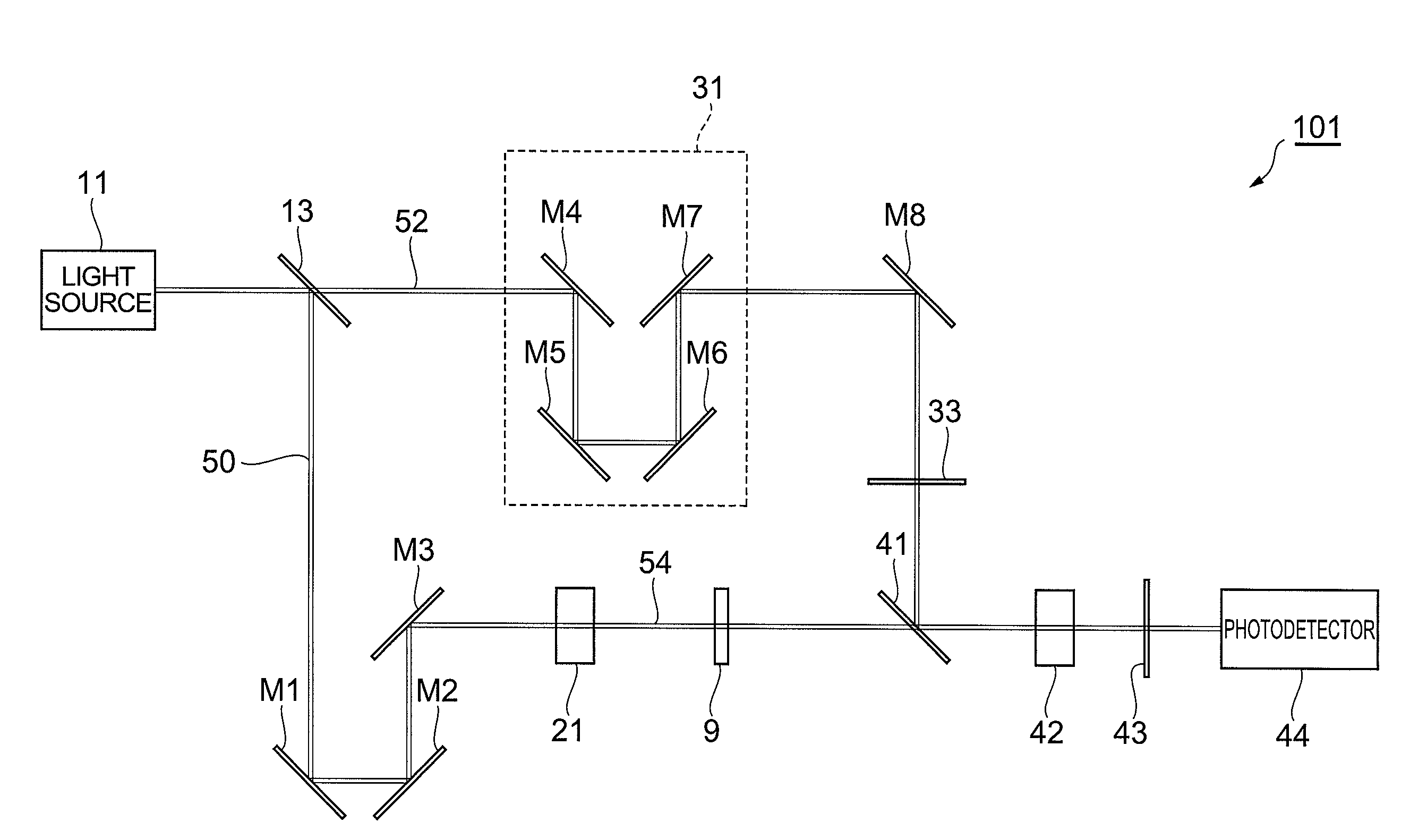
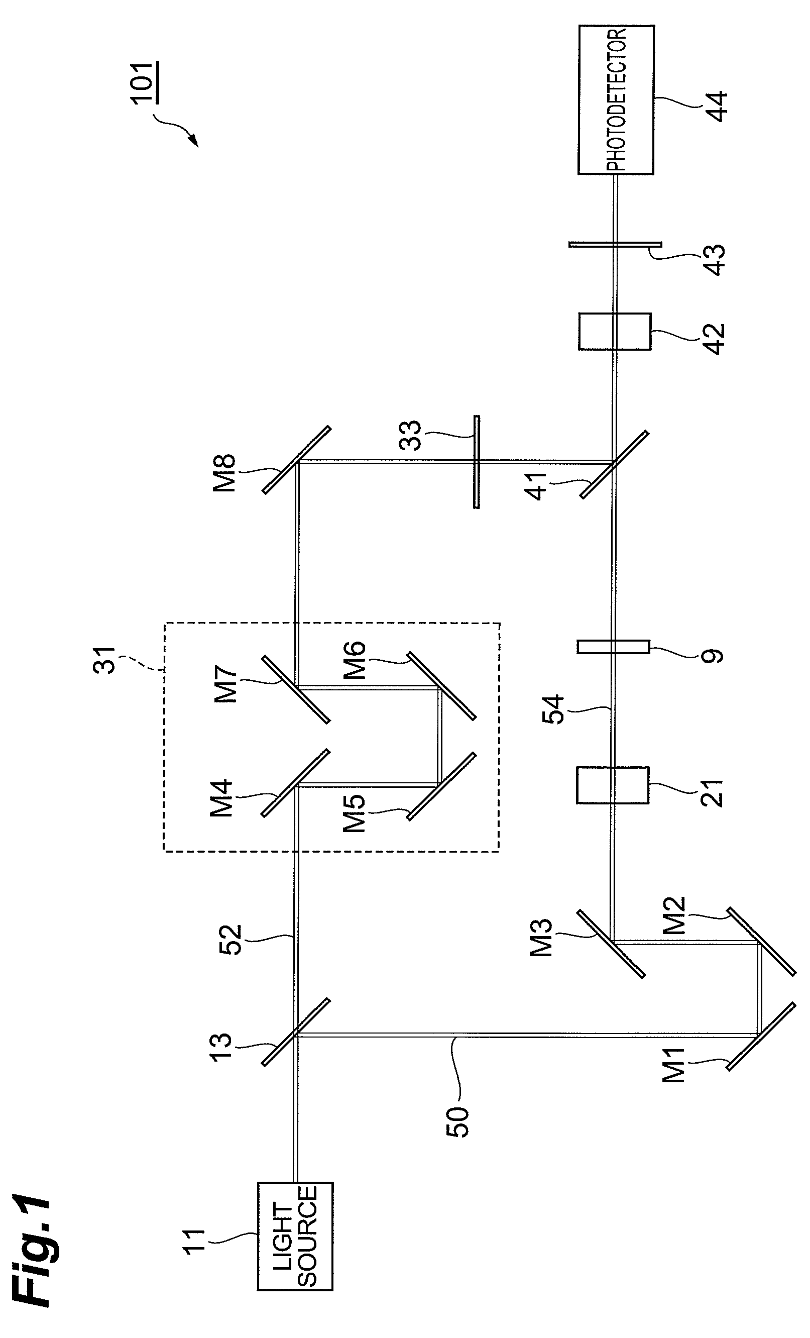
[0037]FIG. 1 is a configuration view of a terahertz wave time-waveform measuring device 101 of a first configuration example. The terahertz wave time-waveform measuring device shown in this figure obtains information on an object to be measured 9 by using a terahertz wave, and includes a light source 11, a separator 13, a terahertz wave generator 21, an optical path length difference adjuster 31, a polarizer 33, a wave synthesizer 41, an electro-optic crystal 42, an analyzer 43, a photodetector 44, and mirrors M1 to M8.

[0038]The light source 11 outputs pulsed light with a predetermined cycle period, and is preferably a femtosecond pulse laser light source which outputs a pulsed laser beam having a pulse width of femtoseconds. The separator 13 is, for example, a beam splitter, and two-separates pulsed light output from the light source 11 and outputs either of the two-separated pulsed lights as a pump light 50 to the mirror M1 and the other as a probe light 52 to the mirror M4.

[0039]...

second configuration example

[0051]FIG. 5 is a configuration view of a single terahertz wave time-waveform measuring device 102 of a second configuration example. The single terahertz wave time-waveform measuring device 102 shown in this figure acquires information on an object to be measured 9 by using a terahertz wave, and includes a light source 11, a beam diameter adjuster 12, a separator 13, a terahertz wave generator 21, a light path length difference adjuster 31, a polarizer 33, an electro-optic crystal 42, an analyzer 43, a photodetector 44, and mirrors M1 to M9.

[0052]In comparison with the configuration of the terahertz wave time-waveform measuring device 101 of the first configuration example shown in FIG. 1, the single terahertz wave time-waveform measuring device 102 of the second configuration example shown in FIG. 5 is different in that a beam diameter adjuster 12 is provided on the light path between the light source 11 and the separator 13, the wave synthesizer 41 is not provided, a mirror M9 is...


PUM

PropertyMeasurementUnit
terahertz wave timeaaaaaaaaaa
birefringenceaaaaaaaaaa
light path lengthaaaaaaaaaa

Abstract

A single terahertz wave time-waveform measuring device 1 acquires information on an object to be measured 9 by using a terahertz wave, and includes a light source 11, a beam diameter adjuster 12, a separator 13, a terahertz wave generator 21, a light path length difference adjuster 31, a pulse front tilting unit 32, a polarizer 33, a wave synthesizer 41, an electro-optic crystal 42, an analyzer 43, and a photodetector 44. The terahertz wave generator 21 generates a pulse terahertz wave in response to an input of pump light and outputs the pulse terahertz wave. The pulse front tilting unit 32 makes pulse fronts of the terahertz wave and the probe light when being input into the electro-optic crystal 42 nonparallel to each other by tilting the pulse front of the probe light.

Description

TECHNICAL FIELD[0001]The present invention relates to a device which measures a time waveform of a terahertz wave transmitted through or reflected by an object to be measured and evaluates characteristics of the object to be measured.BACKGROUND ART[0002]Terahertz waves are electromagnetic waves with a frequency of approximately 0.01 THz to 1000 THz corresponding to an intermediate region between light waves and radio waves, and have intermediate characteristics between light waves and radio waves. As application of such a terahertz wave, a technique for acquiring information on an object to be measured by measuring a time waveform of an electric field amplitude of a terahertz wave transmitted through or reflected by the object to be measured (refer to Non-patent documents 1 to 4) has been studied.[0003]The measuring technique for information on an object to be measured by using a terahertz wave is generally as follows. That is, pulsed light output from a light source (for example, a...

Claims


Application Information

Patent Timeline
Patent Type & Authority Patents(United States)
IPC IPC(8): G01N21/35G01N21/3586
CPCG01N21/23G01N21/35G01N21/3581
Inventor KAWADA, YOICHIYASUDA, TAKASHITAKAHASHI, HIRONORIAOSHIMA, SHINICHIRO
Owner HAMAMATSU PHOTONICS KK
Why Eureka
Try Eureka