Lead frame support plate and window clamp for wire bonding machines

a technology of lead frame support and window clamp, which is applied in the direction of soldering apparatus, manufacturing tools,auxillary welding devices, etc., can solve the problems of floating leads or pads, extremely time-consuming process, and micro-hole formation

Active Publication Date: 2014-06-17
ASMPT SINGAPORE PTE LTD
View PDF37 Cites 6 Cited by
  • Summary
  • Abstract
  • Description
  • Claims
  • Application Information

AI Technical Summary

Benefits of technology

[0008]An advantage of the described embodiment is that with the suction grooves, fabricating time of the lead frame support plate is greatly reduced and yet the suction grooves are able to achieve a balanced suction force on the support surface for holding the lead frame.
[0011]With such a fabrication method, the number of vacuum holes which needs to be formed is greatly reduced since a balanced vacuum force for holding the lead frame is provided by the network of suction grooves.
[0014]An advantage of the described embodiment is that with pair of slots, it is possible to compensate for deformation of the window clamp caused by uneven heat distribution and clamping force asserted to sides of the window clamp during wire bonding. This thus achieves a more effective clamping of leads of a lead frame by the window clamp.
[0015]Preferably, each slot is generally C-shape with arm portions extending respectively from the first and second ends and generally orthogonal to the elongate portion. This configuration has been found to be more effective in compensating for deformation or warpage of the window clamp.

Problems solved by technology

However, forming of the micro-holes 114 is an extremely time-consuming process.
Such deformation would result in loose contact of the window clamp with leads of a lead frame resulting in floating leads or pads due to an insufficient clamping force therebetween.

Method used


Image

  • Lead frame support plate and window clamp for wire bonding machines
  • Lead frame support plate and window clamp for wire bonding machines
  • Lead frame support plate and window clamp for wire bonding machines

Examples


Embodiment Construction

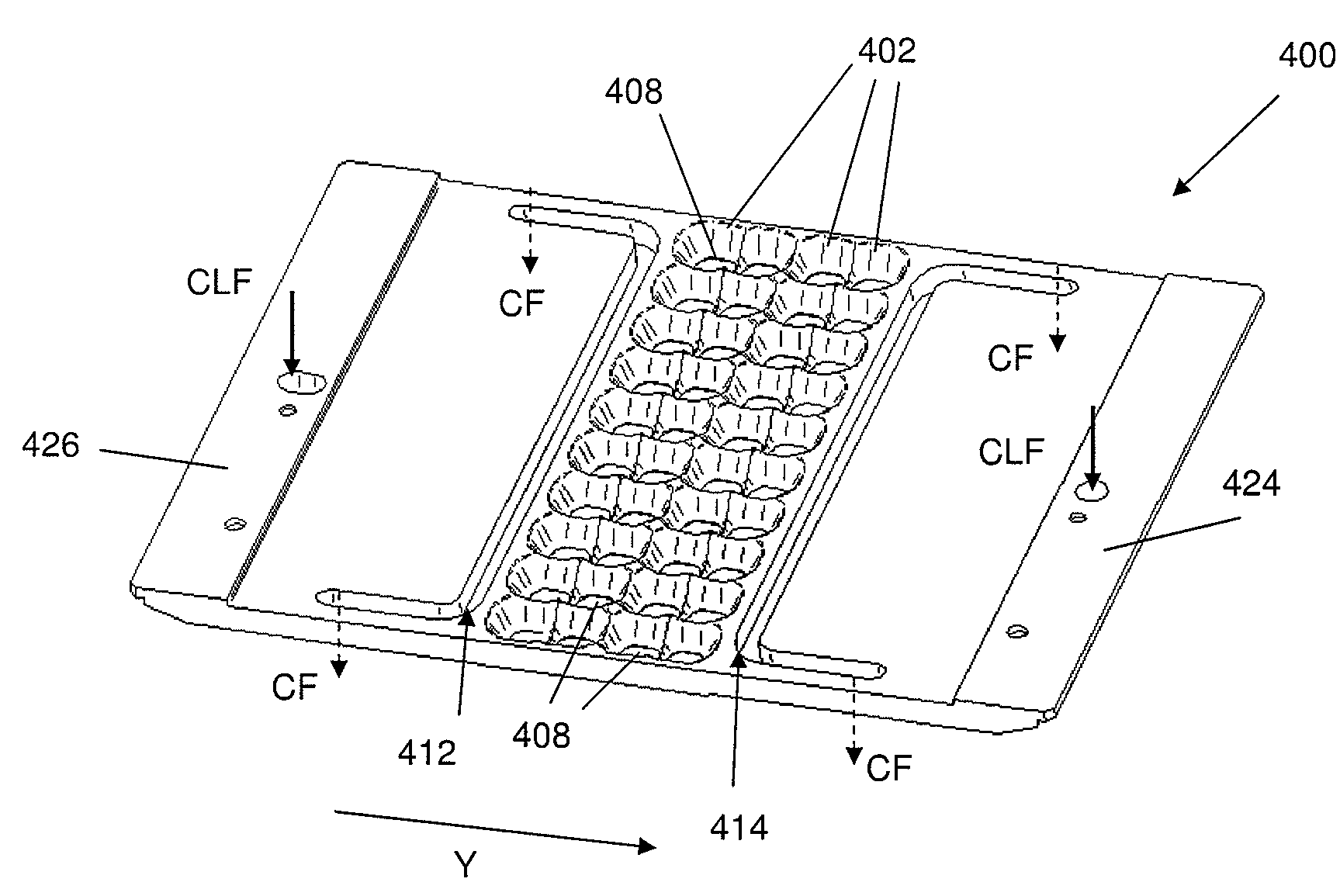
[0032]FIG. 5 shows a lead frame support plate 200 of a preferred embodiment of the present invention. The lead frame support plate 200 includes a generally rectangular body 202 having first and second edges 204, 206 and side sections 208, 210 which define a boundary for a support surface 212 and a bottom surface 214 (see FIG. 8a). Size of the support surface 212 is adapted to accommodate or support a strip of lead frames similar to what is shown in FIGS. 1 and 2.

[0033]A series of side bores (not shown) of diameters about 1.0 mm-1.5 mm are formed using an endmill similar to what is illustrated in FIG. 3. The elongate side bores extend through the body 202 from the first edge 204 to the second edge 206, and the number of side bores are fewer than that illustrated in FIG. 3, for reasons which will be apparent later. The side bores may not only be vertical ones and diagonal side bores are also envisaged.

[0034]Next, an array of vacuum holes 216 are created which are through holes of diam...


PUM

PropertyMeasurementUnit
depthaaaaaaaaaa
temperatureaaaaaaaaaa
diameteraaaaaaaaaa

Abstract

A lead frame support plate 200 and a window clamp 400 for wire bonding machines are disclosed herein. In a described embodiment, the lead frame support plate 200 includes a network of suction grooves 218 provided on a support surface 212, each suction groove 218 being arranged to be in fluid communication with at least a vacuum hole 216 to enable a suction force to be created, in response to a vacuum force, along the network of suction grooves for holding a lead frame against the support surface. A window clamp 400 having slots for compensating deformation of the window clamp and a method of fabricating the lead frame support plate are also disclosed.

Description

BACKGROUND AND FIELD[0001]This invention relates to a lead frame support plate and window clamp for wire bonding machines.[0002]To ensure proper and accurate wire bonding, a lead frame needs to be held in place with respect to a wire bonding machine and FIG. 1 illustrates a conventional approach. FIG. 1 shows part of a wire bonding machine 100 comprising a window clamp 102 placed over a strip of lead frame 104 and a lead frame support plate 106 for supporting the strip of lead frame 104. The window clamp 102 includes two support sections 108 which are held by corresponding window clamp holders 110 for applying a clamping force to the window clamp 102.[0003]FIG. 2 is an enlarged side perspective view of the part of the wire bonding machine 100 of FIG. 1 without showing the window clamp holders 110. The wire bonding machine further includes a heater block 112 for heating the lead frame support plate 106 and thus, the strip of lead frame 104 during the wire bonding process.[0004]FIG. 3...

Claims


Application Information

Patent Timeline
Patent Type & Authority Patents(United States)
IPC IPC(8): B23K37/04
CPCB23P11/00H01L2224/78701H01L2224/78981B23K37/04H01L24/85H01L2924/00014H01L2224/78704H01L24/78B23K20/004Y10T29/49826H01L2224/85H01L2224/78744H01L2224/45099
Inventor CHUANG, PHUI PHOONGHASIM, HASRUL BINAZMI, WANRAMLAN, SITI NURULHAIDA BT.KWAN, KA SHINGHE, TING YUWAN, JUN
Owner ASMPT SINGAPORE PTE LTD
Why Eureka
Try Eureka