
Subsea hydrocarbon production system

a hydrocarbon production system and subsea technology, applied in survey, data switching network, borehole/well accessories, etc., can solve the problems of increasing the cost of subsea umbilicals, prohibitively expensive cost of extending a subsea umbilical to a new subsea well in a new marginal prospect, and practicable limits on the number of subsea wells that can be served by a subsea umbilical

Active Publication Date: 2014-06-24
DEN NORSKE STATS OLJESELSKAP AS
View PDF129 Cites 8 Cited by
  • Summary
  • Abstract
  • Description
  • Claims
  • Application Information

AI Technical Summary

Benefits of technology

The invention is a system for producing oil and gas from underground wells. It includes a main production facility and multiple subsea wells connected through a network. The system also has separate networks for delivering electricity and data, allowing for more flexible use of the wells. The data network uses fiber optic communication for high-speed data transmission without interference from electrical power sources. The subsea nodes can be interconnected for redundancy and load balancing purposes. Overall, this system ensures efficient oil and gas production from underground wells.

Problems solved by technology

A typical subsea umbilical may serve 12 or more subsea wells, but there are practical limits on the number of subsea wells that can be served by a subsea umbilical.
This could greatly increase the costs of subsea umbilicals.
Another problem with existing subsea umbilicals is that the cost of extending a subsea umbilical to a new subsea well in a new marginal prospect can be prohibitively expensive, especially if the subsea well must be connected to a host facility with a new umbilical.
A further problem associated with existing subsea umbilicals is that when a subsea umbilical develops a fault, it can affect all of the subsea wells ‘downstream’ of the fault, and so repairs and upgrades can be expensive in terms of lost production.
This leads to losses in power transmission, which limit the practical length of a subsea umbilical to around 150 km.

Method used


Image

  • Subsea hydrocarbon production system
  • Subsea hydrocarbon production system
  • Subsea hydrocarbon production system

Examples


Embodiment Construction

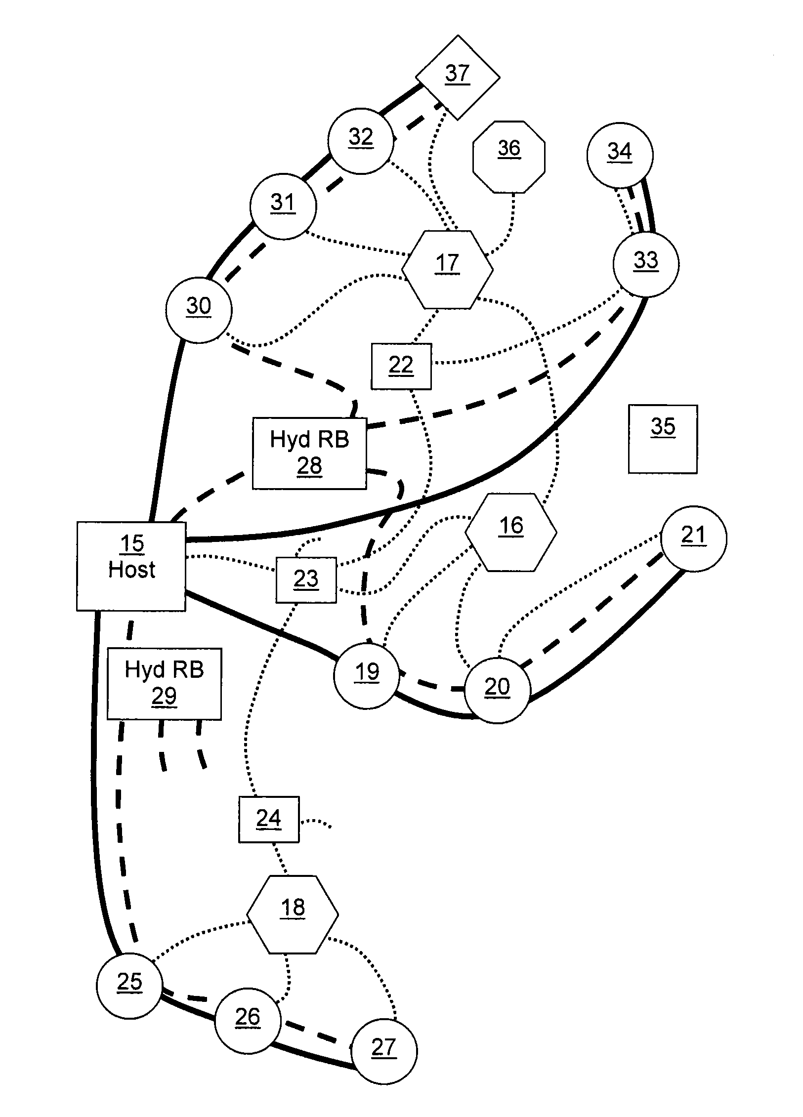
[0031]The inventor has realized that many of the problems associated with prior art subsea umbilicals can be mitigated by separating out the services. According to the present invention, subsea umbilicals are primarily used to convey hydraulic fluid and wellstream service fluids, and are not used to convey electric power to subsea wells or data between a subsea well and a host production facility. A separate electric power and data network is provided. The following description introduces the term “subsea fluid conduit” to refer to a subsea conduit that is used for conveying fluids such as hydraulic fluids and wellstream service fluids, but is not used to convey electric power or data.

[0032]Referring to FIG. 3 herein, a schematic diagram of a plurality of subsea wells connected to a host production facility 15 is illustrated. Pipelines carrying hydrocarbons are illustrated as thick black lines. Subsea fluid conduits are illustrated as thick dashed lines, and a separate network carry...


PUM


Abstract

A subsea oil and / or gas production system comprises a host production facility and a plurality of subsea wells. A fluid conveying network is provided that connects each subsea well to the host production facility. A separate electrical power and data network is provided for conveying direct current electrical power and data, operatively connected to each subsea well for providing each subsea well with data transfer and electrical power services. The use of direct current ensures that the electrical power and data network can provide power over much greater distances than currently available, and the use of separate networks for conveying fluids and for providing electrical power and data transfer allows for a much more flexible system.

Description

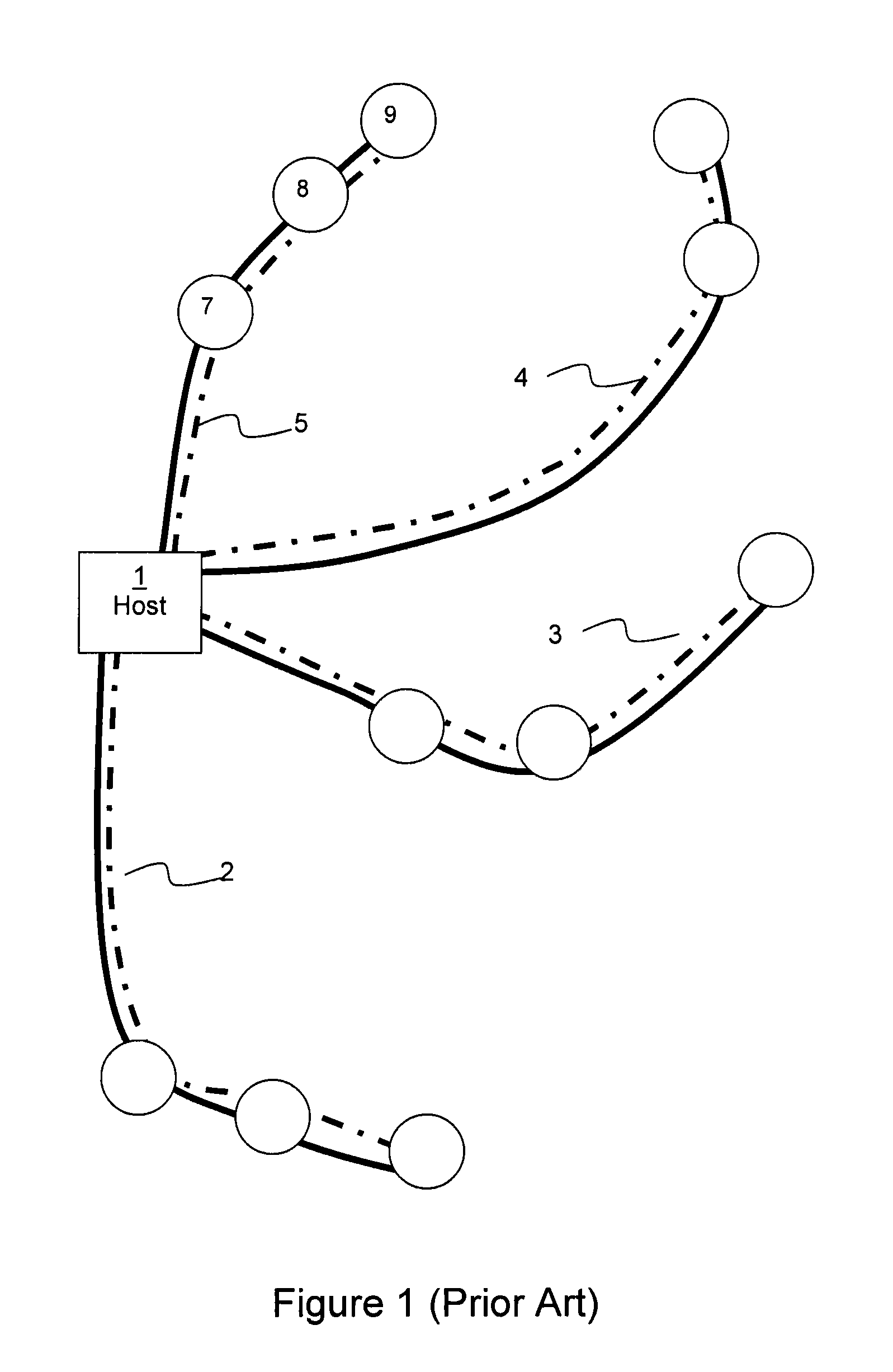
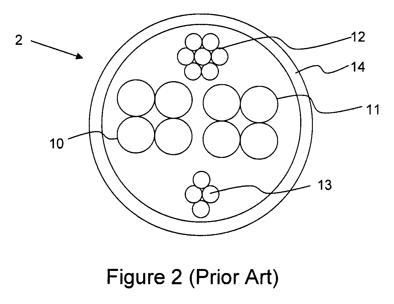
TECHNICAL FIELD[0001]The present invention relates to subsea hydrocarbon production, and in particular to systems for connecting a host production facility to subsea wells.BACKGROUND OF THE INVENTION[0002]In subsea hydrocarbon production systems, a host production facility such as a shore based production facility or an offshore platform is typically connected to one or more subsea wells. Production pipelines connect each subsea well to the host production facility. Production pipelines are used for conveying extracted hydrocarbons back to the host production facility. In addition to the production pipelines, it is necessary to provide each subsea well with certain services. These may include electric power, data transfer, hydraulic fluids and wellstream service fluids, such as chemical additives. These four services are normally provided in a subsea umbilical.[0003]Referring to FIG. 1 herein, there is illustrated schematically a network of subsea wells connected to a host productio...

Claims


Application Information

Patent Timeline
Patent Type & Authority Patents(United States)
IPC IPC(8): E21B43/01
CPCE21B47/12E21B43/017E21B43/01E21B17/02H04L12/10H04L12/40045E21B17/003E21B17/01E21B19/002E21B43/0107
Inventor STENEVIK, KARL-ATLE
Owner DEN NORSKE STATS OLJESELSKAP AS
Learn More