In vivo inflatable structures, for example to expand stents

a technology of inflatable structures and stents, which is applied in the field of inflatable devices, can solve the problems of sharp or unnatural configurations or discontinuities, unsmooth changes in direction, and increase and achieve the effects of high straightening force, overcoming the rigidity of inflated states, and increasing the risk of further blockag

Inactive Publication Date: 2014-06-24
GELBART DANIEL +1
View PDF20 Cites 3 Cited by
  • Summary
  • Abstract
  • Description
  • Claims
  • Application Information

AI Technical Summary

Benefits of technology

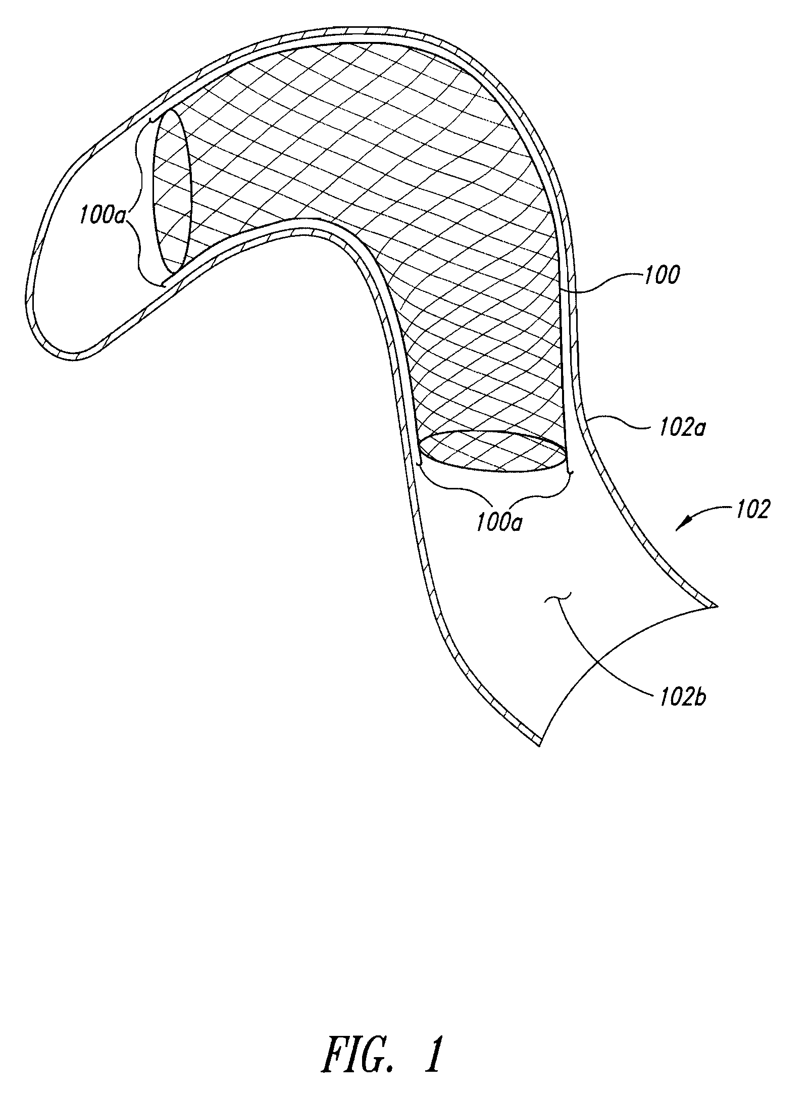
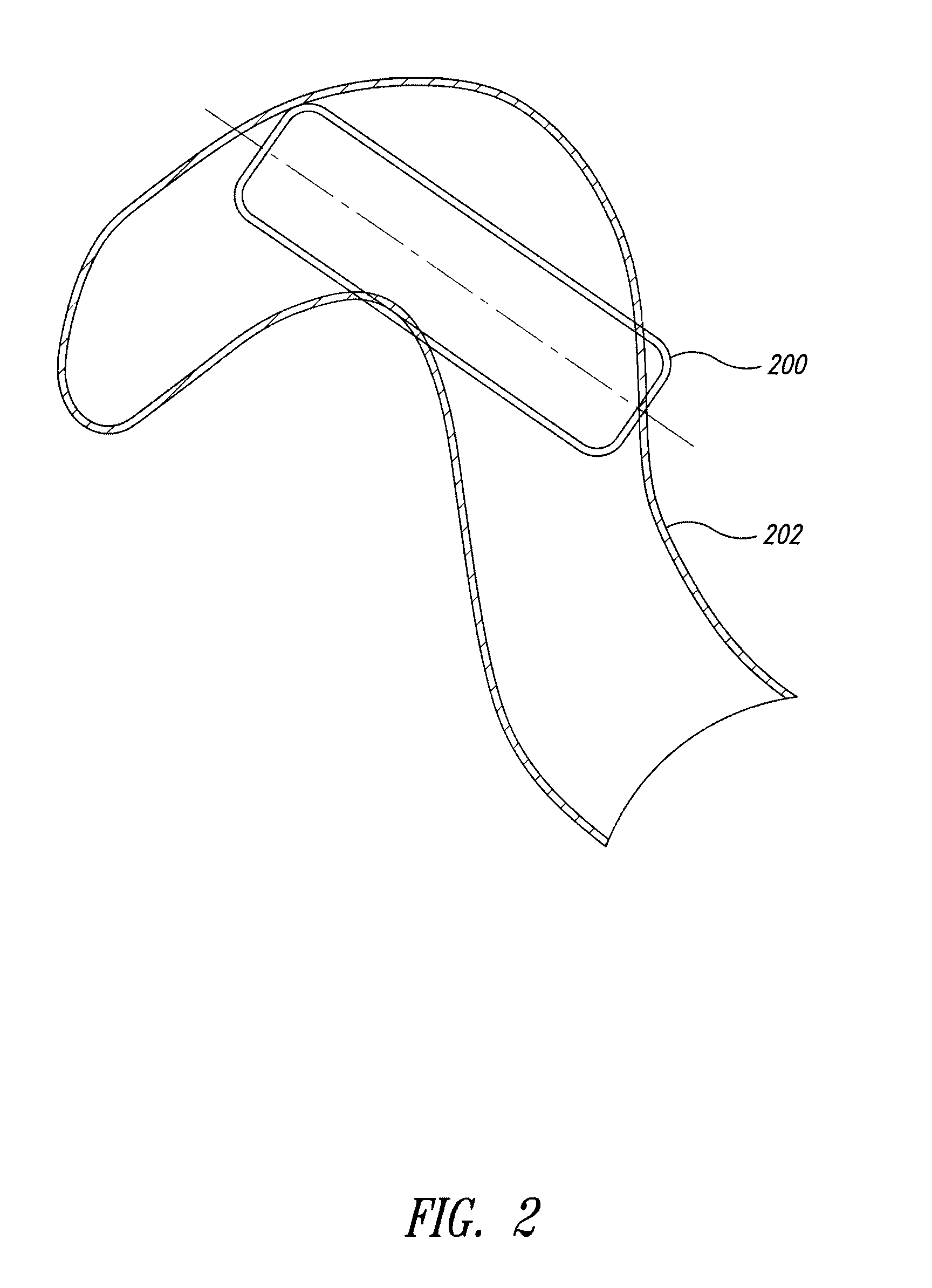
[0009]Applicants have recognized that it may be advantageous to perform angioplasty and / or implant a stent over an appreciable length of vasculature. Applicants have also recognized that existing balloons are too rigid to easily travel the tortuous path of some lumens, for example some vasculature. Applicants have further recognized that existing balloons apply a high straightening force when used over an appreciable length of a lumen such as vasculature, therefore significantly deforming the vasculature, resulting in sharp or unnatural configurations or discontinuities (e.g., unsmooth changes in direction) of the vasculature. At least some scientific literature suggests that sharp or abrupt angles in vasculature may lead to medical problems, for example increasing the risk of further blockages. Applicants have additionally recognized that existing balloons, when inflated, are too rigid to apply a uniform force over an entire length of a flexible stent or over multiple stents, particularly when the position of the stent or stents is in a tortuous section of the lumens such as vasculature. Balloons made of elastic material, in attempt to overcome the rigidity in inflated states, are unstable as they tend to inflate excessively in less restrictive areas and not keep the desired tubular shape. Maintaining of a tubular shape with high force and high uniformity of radial expansion, but with low bending stiffness is highly desirable. In conventional inflated balloon, such properties are contradictory. For example, when a balloon is made of inelastic material, the bending force is too high when the balloon is inflated. However if a balloon is made of very elastic material, radial expansion is irregular and not self limiting. When a balloon is made in the shape of a bellows, the bellows shape is imparted to the expanded stent, which is undesirable. Applicants have further recognized that it may be advantageous to employ such balloons in a variety of bodily lumens other than vasculature, including but not limited to: airways, bronchi, trachea; gastro-intestinal such as the esophagus, stomach, intestines for instance the small intestine and / or colon (e.g., ascending, transverse, descending, sigmoid) and rectum; hepatobiliary structures (e.g., common bile duct, inter-hepatic ducts); genitourinary (ureters, urethral, prostatic, fallopian tubes, uterine); sinuses (frontal, ethmoid) and / or lymphatic structure.
[0017]At least one embodiment may be summarized as a medical article including a plurality of inflatable balloons sized to be received in a bodily lumen, for example intravascularly, in at least partially overlapping relation; and a lubricant carried by at least one of the inflatable balloons to lower a friction coefficient between the inflatable balloons in at least a partially inflated state.

Problems solved by technology

Applicants have further recognized that existing balloons apply a high straightening force when used over an appreciable length of a lumen such as vasculature, therefore significantly deforming the vasculature, resulting in sharp or unnatural configurations or discontinuities (e.g., unsmooth changes in direction) of the vasculature.
At least some scientific literature suggests that sharp or abrupt angles in vasculature may lead to medical problems, for example increasing the risk of further blockages.
Applicants have additionally recognized that existing balloons, when inflated, are too rigid to apply a uniform force over an entire length of a flexible stent or over multiple stents, particularly when the position of the stent or stents is in a tortuous section of the lumens such as vasculature.
Balloons made of elastic material, in attempt to overcome the rigidity in inflated states, are unstable as they tend to inflate excessively in less restrictive areas and not keep the desired tubular shape.
For example, when a balloon is made of inelastic material, the bending force is too high when the balloon is inflated.
When a balloon is made in the shape of a bellows, the bellows shape is imparted to the expanded stent, which is undesirable.

Method used


Image

  • In vivo inflatable structures, for example to expand stents
  • In vivo inflatable structures, for example to expand stents
  • In vivo inflatable structures, for example to expand stents

Examples


Embodiment Construction

[0075]In the following description, certain specific details are set forth in order to provide a thorough understanding of various disclosed embodiments. However, one skilled in the relevant art will recognize that embodiments may be practiced without one or more of these specific details, or with other methods, components, materials, etc. In other instances, well-known structures associated with stents, catheters, balloons, fluid delivery subsystems and / or image based or other location determination subsystems have not been shown or described in detail to avoid unnecessarily obscuring descriptions of the embodiments.

[0076]Unless the context requires otherwise, throughout the specification and claims which follow, the word “comprise” and variations thereof, such as, “comprises” and “comprising” are to be construed in an open, inclusive sense, that is as “including, but not limited to.”

[0077]Reference throughout this specification to “one embodiment” or “an embodiment” means that a p...


PUM

PropertyMeasurementUnit
anglesaaaaaaaaaa
anglesaaaaaaaaaa
anglesaaaaaaaaaa

Abstract

Multi-balloon catheter structures that are able to move with respect to one another may provide superior compliance in tortuous passages to, for example, perform angioplasty and / or expand stents. Two or more balloons may be inflated to equal pressures. A length of the balloons may be sufficiently longer than a length of a stent to accommodate axial movement of the balloons. One or more balloons may be lubricous or carry a lubricant.

Description

BACKGROUND[0001]1. Technical Field[0002]The present disclosure is related to in vivo medical devices, and more particularly to inflatable devices for use in bodily vessels or lumens, for example vasculature such as arteries.[0003]2. Description of the Related Art[0004]Numerous medical procedures now employ catheters to enter bodily vessels, for example vasculature such as arteries, veins, and or the heart. Such procedures are often percutaneous, providing numerous advantages over more traditional surgery, for example reduced trauma and faster healing. However, catheter procedures are often difficult to perform. Catheter procedures require a care provider (e.g., medical doctor or physician) to guide a catheter or guide wire through the vasculature to a desired position without direct visual feedback. The care provider may receive tactile feedback and / or secondary visual feedback. The secondary visual feedback may come from a camera mounted to the catheter or guide wire. The secondary...

Claims


Application Information

Patent Timeline
Patent Type & Authority Patents(United States)
IPC IPC(8): A61M29/00
CPCA61M2025/1088A61M2025/1015A61M29/02A61M25/1002A61M25/1011A61M25/1027A61M25/1038Y10T29/49826
Inventor GELBART, DANIELRUST, MATTHEW J.
Owner GELBART DANIEL
Why Eureka
Try Eureka