
Liquid material vaporizer

a liquid material and vaporizer technology, applied in the field of vaporizers, can solve the problems of deterioration of parts of precursors, clogging or particle nozzles, and inability to continue vaporization, so as to prevent residues, prevent clogging of nozzles, and reduce risks

Active Publication Date: 2014-07-01
HORIBA STEC CO LTD
View PDF14 Cites 6 Cited by
  • Summary
  • Abstract
  • Description
  • Claims
  • Application Information

AI Technical Summary

Benefits of technology

[0017]In accordance with this invention, vaporization can be conducted at a lower temperature compared with a conventional vaporizer so that it is possible to prevent a residue due to thermal decomposition of the precursor and to prevent clogging of the nozzle. Conversely, if the temperature is set at the same as that of the conventional vaporizer, it is possible for the vaporizer of this invention to flow much more of the precursor, namely a large amount of precursor flow can be flown.
[0018]Furthermore, even if one nozzle is clogged, the precursor can flow from another nozzle so that it is possible to reduce a risk that the operation is completely halted.

Problems solved by technology

As a result, the following problem is generated more than ever before.
However, since the liquid precursor is easy to be thermally decomposed, if exposed to high temperature in order to vaporize, a part of the precursor is deteriorated so as to be a residue.
As a result, the nozzle might be clogged or a particle might be produced.
Furthermore, since a conventional vaporizer is of a single nozzle structure, if a nozzle is clogged, there would be a problem in that it becomes impossible to continue vaporization, and operation is halted almost completely.
As a result, thermal decomposition of the precursor is likely to be caused.

Method used


Image

  • Liquid material vaporizer
  • Liquid material vaporizer
  • Liquid material vaporizer

Examples


Embodiment Construction

[0033]One embodiment of the present claimed invention will be explained with reference to the drawings.

[0034]A vaporizer A in accordance with this embodiment constitutes a part of, for example, a semiconductor manufacturing system (not shown in the drawings) and has a function of providing a precursor for forming a semiconductor element in a gaseous phase by being connected to a vacuum chamber (not shown in the drawings).

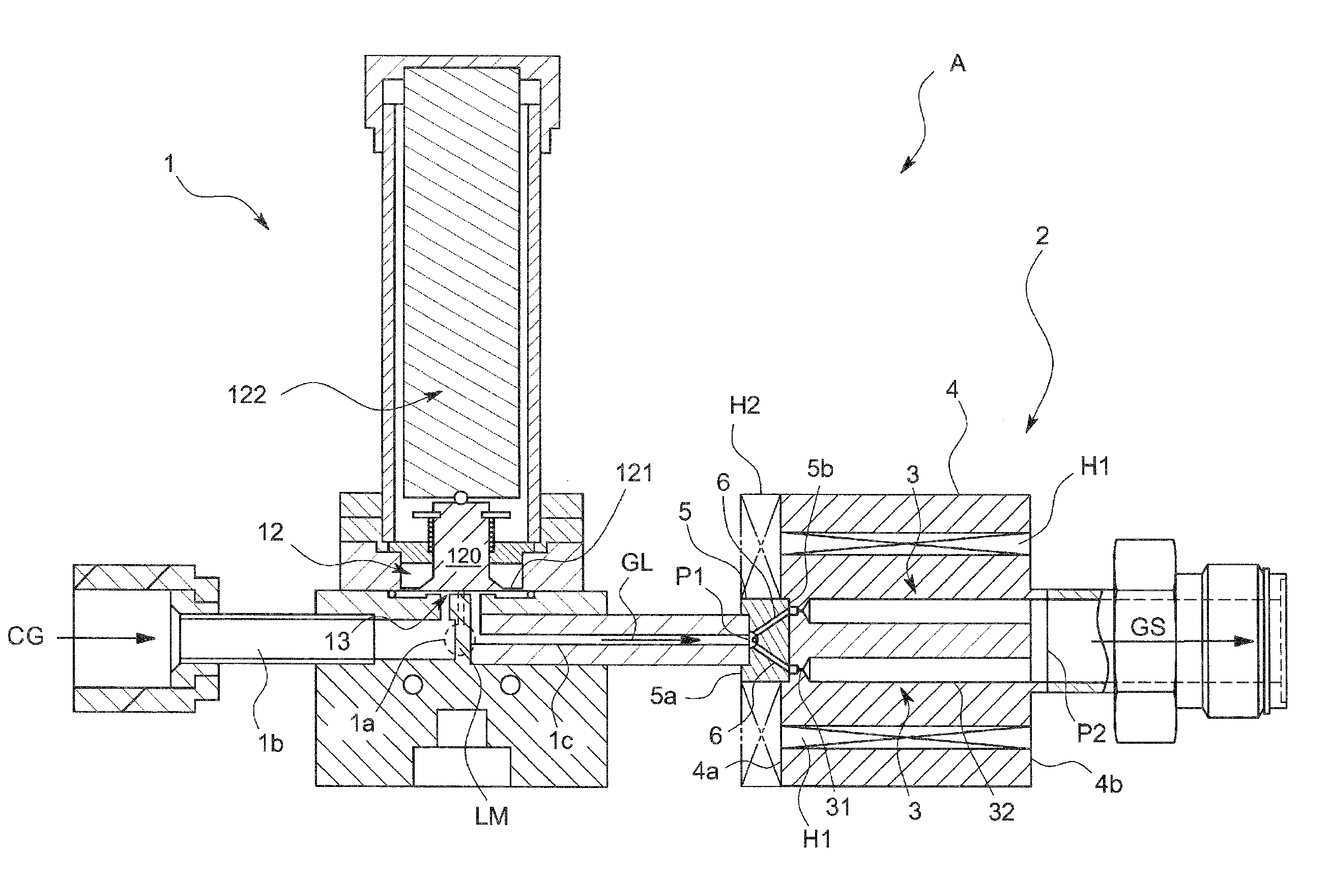
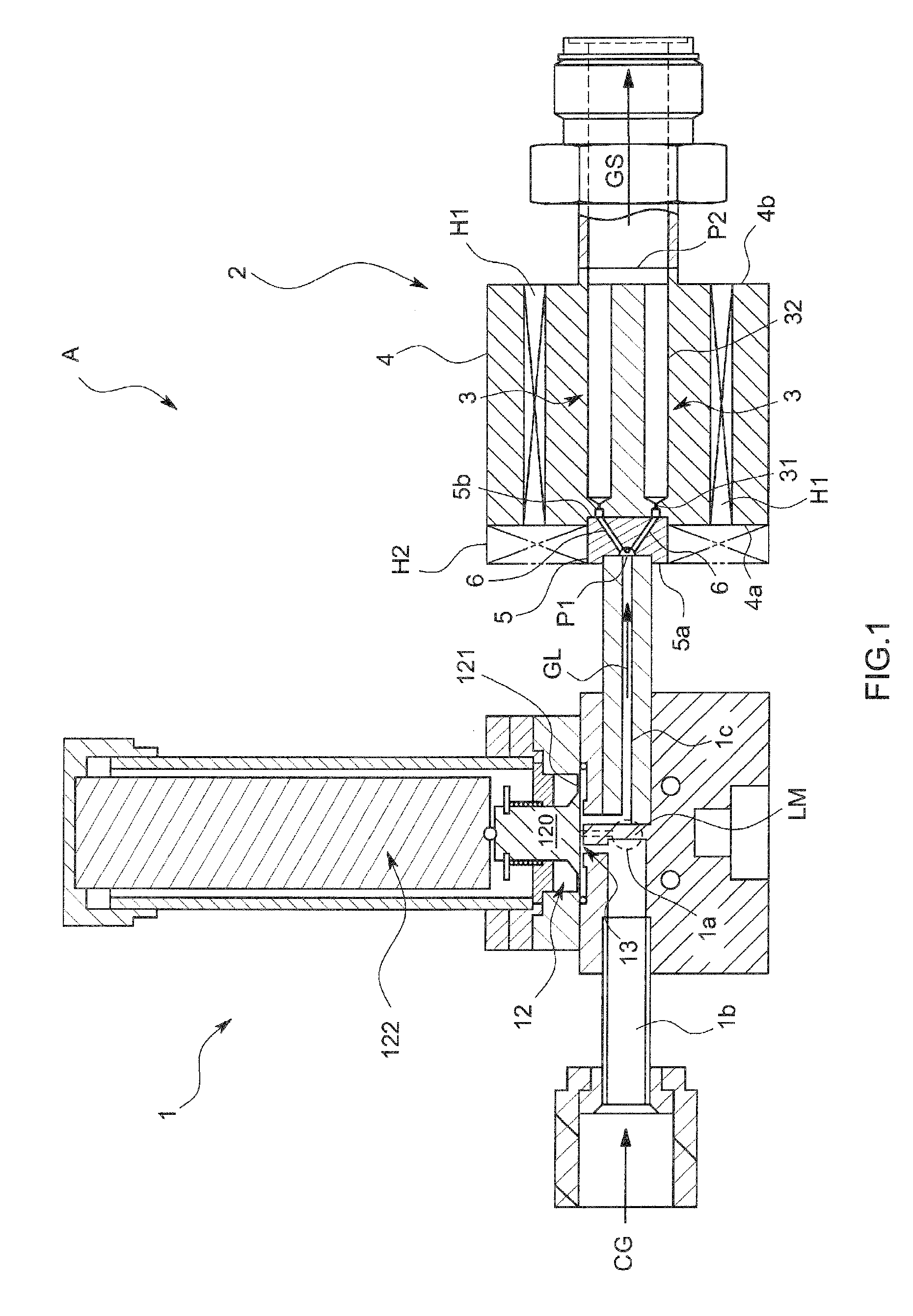
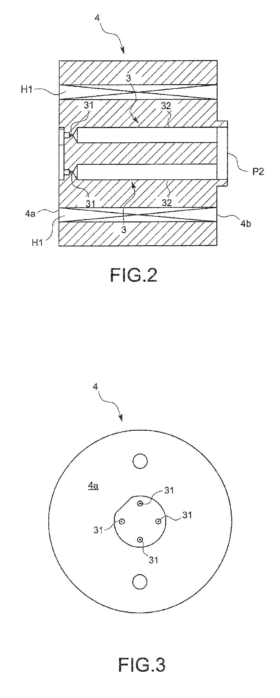
[0035]Concretely, the vaporizer A comprises, as shown in FIG. 1, a vapor liquid mixing mechanism 1 that mixes the precursor (also refer to as a liquid precursor) LM in a liquid phase with a carrier gas CG so as to produce a gas-liquid mixture GL, and a vaporizing body mechanism 2 that vaporizes the liquid precursor LM contained in the gas-liquid mixture GL so as to make it in a state of a gas phase (also referred to as a precursory gas) and then to discharge the precursory gas GS outside, namely into a vacuum chamber together with the carrier gas CG.

[0036]First, the...


PUM

PropertyMeasurementUnit
temperatureaaaaaaaaaa
vapor pressureaaaaaaaaaa
temperatureaaaaaaaaaa

Abstract

This invention provides a vaporizer that prevents deterioration of a precursor while reducing a residue, that can expect reduction in risk of clogging, and that can increase vaporization flow easily. The vaporizer comprises an inlet port for introducing a precursor in a liquid phase or a gas-liquid mixture phase, a vaporizing section for vaporizing the precursor arranged on the downstream side of the inlet port, and an outlet port for delivering the precursor vaporized at the vaporizing section, wherein the vaporizing section is of a flow channel type comprising a nozzle for spraying the precursor and a heating channel arranged on the downstream side of the nozzle continuously thereto. A plurality of vaporizing sections are arranged in parallel between the inlet port and the outlet port, and arranged such that each vaporizing section can distribute the precursor independently of each other.

Description

FIELD OF THE ART[0001]This invention relates to a vaporizer for vaporizing various kinds of a liquid precursor used for, for example, a semiconductor manufacturing process.BACKGROUND ART[0002]Conventionally, this kind of vaporizer has an arrangement wherein a gas-liquid mixture comprising a liquid precursor and a carrier gas used for forming a film is discharged from a nozzle so as to be depressurized, and then heat is applied by a heating channel arranged on a downstream side of the nozzle so as to vaporize the liquid precursor (patent document 1).[0003]However, some liquid material, that is often used as a precursor for high-k process, of a recent semiconductor element has a property of being easy to be thermally decomposed and has low vapor pressure. As a result, the following problem is generated more than ever before.[0004]More specifically, the liquid precursor has to be at a high temperature in order to be vaporized because it has a low vapor pressure. However, since the liqu...

Claims


Application Information

Patent Timeline
Patent Type & Authority Patents(United States)
IPC IPC(8): B05B1/24B01B1/00B01B1/06C23C16/448
CPCC23C16/4486B01B1/005B01B1/06B01J7/02
Inventor NISHIKAWA, ICHIROKAWANO, TAKESHI
Owner HORIBA STEC CO LTD
Learn More