Method for converting a blow molding machine and blow molding machine

a blow molding machine and conversion method technology, applied in the direction of molds, manufacturing tools, ceramic shaping apparatus, etc., can solve the problem that the achievable minimization of production loss is negligible with the addition of efforts, and achieve the effect of minimizing production loss

Active Publication Date: 2014-07-15
KRONES AG
View PDF13 Cites 0 Cited by
  • Summary
  • Abstract
  • Description
  • Claims
  • Application Information

AI Technical Summary

Benefits of technology

[0008]It is an aspect of the present disclosure to indicate a method of the aforementioned type as well as a blow molding machine for minimizing production loss caused by conversion due to a mold change.
[0010]According to the method each heat-set mold is optionally cooled not only by the heat carrier of the temperature control devices that is circulating through the mold without any further heat supply, but in addition during at least one simulated work cycle by externally supplied cooling medium that efficiently removes heat from the mold via the mold cavity surface and discharges said heat. Surprisingly, the waiting period until the molds have reached temperatures suited for handling can be reduced by about half the time or even more, whereby production loss caused by conversion due to mold change is minimized. At least one simulated work cycle is here carried out with empty molds so that all molds are cooled evenly and simultaneously, and drive and movement control mechanisms of the blow molding machine that exist at any rate can here be used in a profitable way. The only additional measure that is needed consists in providing and introducing the cooling medium in a sufficient quantity, optionally at an increased pressure intensifying the cooling action and at a corresponding feed rate. These additional efforts, however, are negligible with respect to the achievable minimization of the production loss. The heat discharge by means of the cooling medium from the mold cavity surface is surprisingly efficient, and flow paths to the mold cavity that exist at any rate can be used without significant modifications on the molds or the further equipment of the blow molding machine for the additional cooling operation. As an alternative, the cooling medium could also circulate in supply and / or discharge paths only provided for forced cooling, by means of a conveying device that is also provided for this purpose alone. According to the method a plurality of simulated work cycles are carried out in successive order, if necessary, with the blow molding machine continuing to run “empty” until the mold temperature desired for the mold change has been reached.
[0011]Apart from equipment provided at any rate, the blow molding machine needs substantially only a program routine in the machine control to carry out at least one simulated work cycle with empty molds to prepare a converting process and to convey the cooling medium, optionally at the same time, into the mold cavities of all molds. Expediently, the at least one simulated work cycle with empty molds is here carried out at a rotational speed of the molds reduced in comparison with the normal work cycles and thus with a reduced energy input. Apart from this, the blow molding machine, particularly a heat-set stretch blow-molding machine, does possibly not require any significant modifications. The temperature control devices provided for the heat set blow-molding operation do not heat the heat carrier used for temperature control in the simulated work cycle because they are activated only for a normal work cycle or for heating, so that the additional cooling by the externally supplied cooling medium effects a rapid reduction of the mold temperature in comparison with the heat-set operating temperature, and the molds can already be exchanged after a very short period. For instance, ambient air is used for cooling on the mold cavity surface. The ambient air can optionally be cooled in an active way to enhance the cooling effect. Alternatively, a liquid cooling medium, such as cooling water, could also be used, or a mixture of gaseous and liquid cooling media, e.g. in aerosol form, to intensify the cooling effect by removal of evaporation heat from the mold cavity surface.
[0016]The aforementioned method variants can also be combined with one another to make the cooling action as efficient as possible.
[0020]Expediently, the blow molding machine is equipped such that the program routine for each simulated work cycle within one rotation varies the angular range of the medium delivery and / or the delivery pressure or the delivery rate in comparison with a normal work cycle, and / or stationarily stops the stretching rod at a predetermined cooling position in the mold at least substantially. This does not require any significant structural modifications of the blow molding machine, but this can be programmed comfortably at the control side.

Problems solved by technology

These additional efforts, however, are negligible with respect to the achievable minimization of the production loss.

Method used


Image

  • Method for converting a blow molding machine and blow molding machine
  • Method for converting a blow molding machine and blow molding machine

Examples


Embodiment Construction

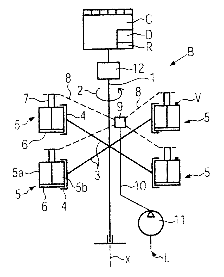
[0027]FIG. 1 is a schematic diagram showing a blow molding machine B for producing plastic containers, such as PET bottles, from preforms, with the containers being continuously produced in normal work cycles of the blow molding machine B, and each work cycle including e.g. a rotation of the blow molding machine B over 360 degrees. Expediently, the blow molding machine B is a heat set type stretch blow molding machine for producing PET bottles for drinks to be filled in a hot state. This means that prior to start of production the molds of the blow molding machine B are heated up to a heat-set operating temperature of e.g. about 130° C. to 180° C. by means of temperature control devices (not shown) and by a heat carrier e.g. circulatingly conveyed through the molds in channels separated from the mold cavity, and are held at said temperature. In stretch blow molding, each preform is mechanically stretched in the blow molding process and blow molded in the mold while supplied with blo...


PUM

PropertyMeasurementUnit
pressureaaaaaaaaaa
pressureaaaaaaaaaa
temperatureaaaaaaaaaa

Abstract

A method for converting a blow molding machine with a plurality of rotatingly movable molds heated to a heat-set operating temperature, due to mold change, having at least one simulated work cycle carried out in the blow molding machine with molds left empty, and a cooling medium then simultaneously supplied to all mold cavities from the outside so as to cool the molds in comparison with the heat-set operating temperature. In a machine control the blow molding machine has a program routine for performing at least one simulated work cycle with empty molds and at a reduced rotational speed of the molds with external supply of a cooling medium into the molds.

Description

CROSS-REFERENCE TO RELATED APPLICATION[0001]The present application claims the benefit of priority of German Application No. 102009031154.8, filed Jun. 30, 2009. The entire text of the priority application is incorporated herein by reference in its entirety.FIELD OF THE DISCLOSURE[0002]The present disclosure relates to a method and to a blow molding machine.BACKGROUND[0003]In heat-set blow molding machines, e.g. for PET bottles for beverages to be filled in a hot state, the molds are additionally heated up by temperature control devices with a heat carrier medium to a heat-set operating temperature. For converting the heat-set blow molding machine to a different type of bottle the molds must be exchanged. A heat-set blow molding machine contains, for example, at least eight molds, or up to thirty molds or more. The heat-set operating temperature may be about 130° C. to 180° C., so that upon a mold change one must first wait until the molds have cooled down to a handling temperature ...

Claims


Application Information

Patent Timeline
Patent Type & Authority Patents(United States)
IPC IPC(8): B28B7/04
CPCB29C31/006B29C33/36B29C35/16B29C49/12B29C49/36B29C49/42B29C49/4252B29C49/4823B29C49/62B29C49/66B29C49/78B29C2035/1616B29C2035/1658B29C2035/1691B29C2049/4856B29C2049/6661B29C2049/6669B29C49/42407B29C49/6605
Inventor HIRDINA, JOCHEN
Owner KRONES AG
Why Eureka
Try Eureka