Method of operating a hybrid power plant to optimise pv power output

a hybrid power plant and power output technology, applied in the direction of pv power plants, wind motors with solar radiation, machines/engines, etc., can solve the problems of affecting the pv modules, and further reducing the total pv power output, so as to achieve the effect of optimizing the power output of the pv modules

Pending Publication Date: 2021-06-24
VESTAS WIND SYST AS
View PDF1 Cites 0 Cited by
  • Summary
  • Abstract
  • Description
  • Claims
  • Application Information

AI Technical Summary

Benefits of technology

[0006]According to a first aspect of the present invention there is provided a method of operating a hybrid power plant comprising at least one WTG and at least one PV module, wherein at least one of the PV modules is at a location within the hybrid power plant that is affected by blade shadows, the method comprising: monitoring at least one operating parameter for one or more of the WTGs; monitoring at least one operating parameter for one or more of the PV modules; and controlling operation of the WTGs in dependence on the monitored operating parameters in order to control blade shadows cast by the WTGs on the PV modules and thereby optimise the power output of the PV modules.
[0007]By taking the effects of the blade shadows cast by the WTGs on the PV modules into account when controlling operation of the WTGs it is possible to increase the power output of the PV modules to an optimum extent, for example by reducing the blade shadow area on the PV modules, while also minimising WTG production loss. The present invention therefore allows the combined power output of the hybrid power plant (including WTG power output and PV power output) to be increased across a broad range of operating conditions compared to the combined power output that would be achieved if the WTGs were controlled to optimise and / or maximise WTG power output in a conventional manner without taking into account the effects of blade shadows on the power output of the PV modules.
[0009]It will also be appreciated that controlling operation of the WTGs in order to optimise the power output of the PV modules does not necessarily mean that the WTGs are controlled in such a manner that the blade shadow area on the PV modules is reduced to the minimum possible level so that the power output from the PV modules can be increased to the highest possible level, which would generally require the WTGs to be stopped or operated in a highly compromised manner that would generally lead to a reduction in combined power output. Instead it means that the WTGs, where appropriate, are operated in such a manner that the negative effect of the blade shadows on the PV modules is reduced such that the power output of the PV modules can be increased to an optimum level while still maintaining an acceptable power output from the WTGs, thereby allowing the combined power output of the hybrid power plant to be optimised and / or maximised.
[0018]The step of controlling operation of the WTGs may comprise determining whether or not performing a particular WTG control operation would increase or decrease the combined WTG and PV power output of the hybrid power plant, and performing the WTG control operation if it is determined that doing so would increase the combined WTG and PV power output of the hybrid power plant. The WTG control operation may, for example, comprise changing the nacelle yaw angle and / or the blade pitch angle for one or more of the WTGs and / or stopping one or more of the WTGs in order to optimise the power output of the PV modules by reducing the shadow area cast on the PV modules by the rotors of the one or more WTGs.

Problems solved by technology

However, when PV modules are located close to WTGs in a hybrid power plant the PV modules may be affected by shadows cast by the WTGs, including static shadows cast by the WTG towers and moving or flickering shadows cast by the blades of the WTG rotors.
For example, tower shadows and blade shadows may reduce the amount of light falling on the PV modules and therefore reduce total PV power output.
In addition, moving blade shadows may also result in sub-optimal functioning of the PV modules' Maximum Power Point Tracking systems, thereby reducing total PV power output further.
In addition, uneven loading of the PV modules due to different shading conditions at different locations caused by the tower shadows and blade shadows can also lead to accelerated degradation of the PV modules.

Method used


Image

  • Method of operating a hybrid power plant to optimise pv power output
  • Method of operating a hybrid power plant to optimise pv power output
  • Method of operating a hybrid power plant to optimise pv power output

Examples


Embodiment Construction

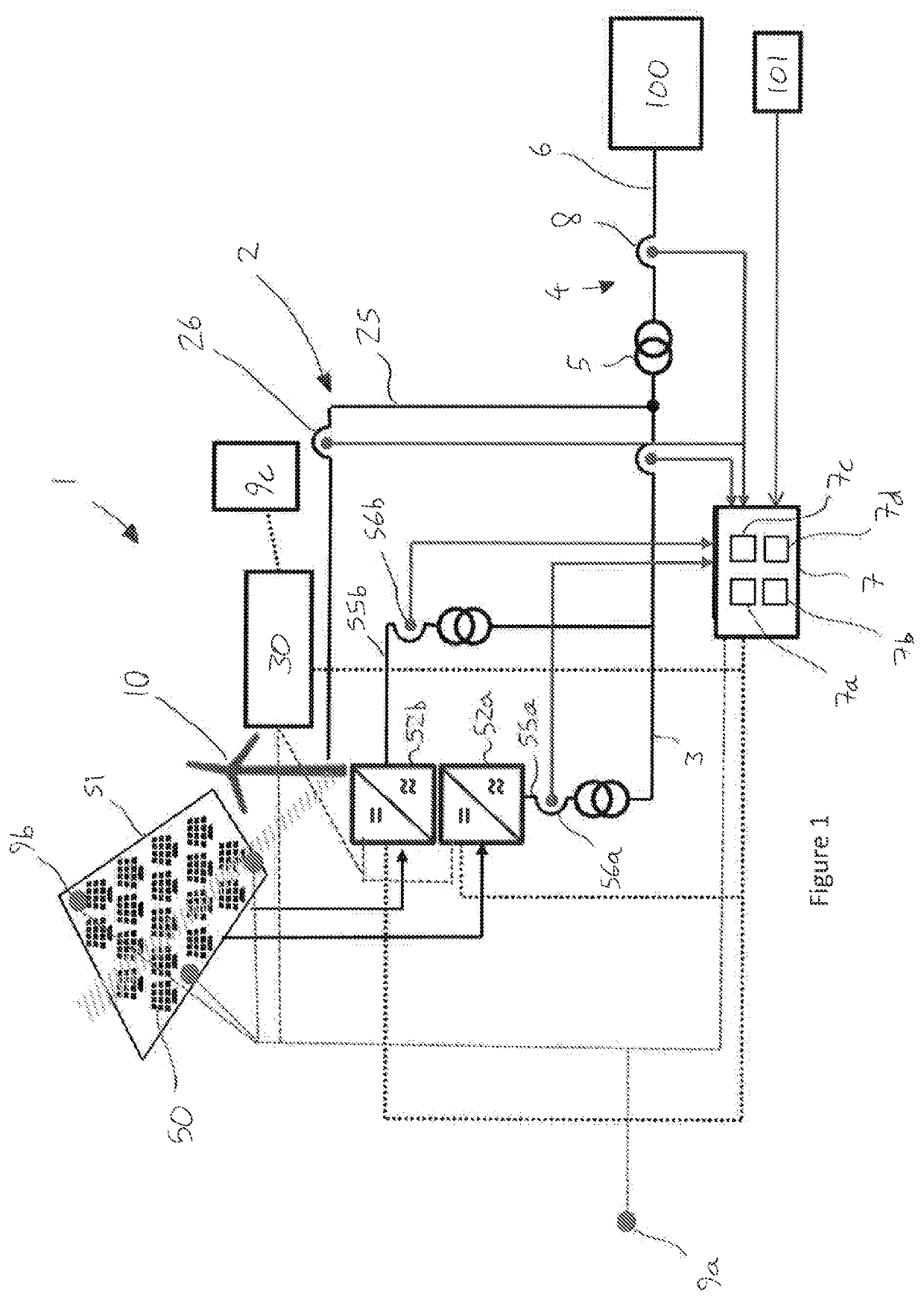
[0034]FIG. 1 schematically illustrates a simplified view of a portion of a hybrid power plant (HPP) 1 in accordance with an embodiment of the present invention. The HPP 1 is connected to an external power transmission network or main grid 100. The main grid 100 may be a regional, national or international power transmission network, for example the National Grid of Great Britain.

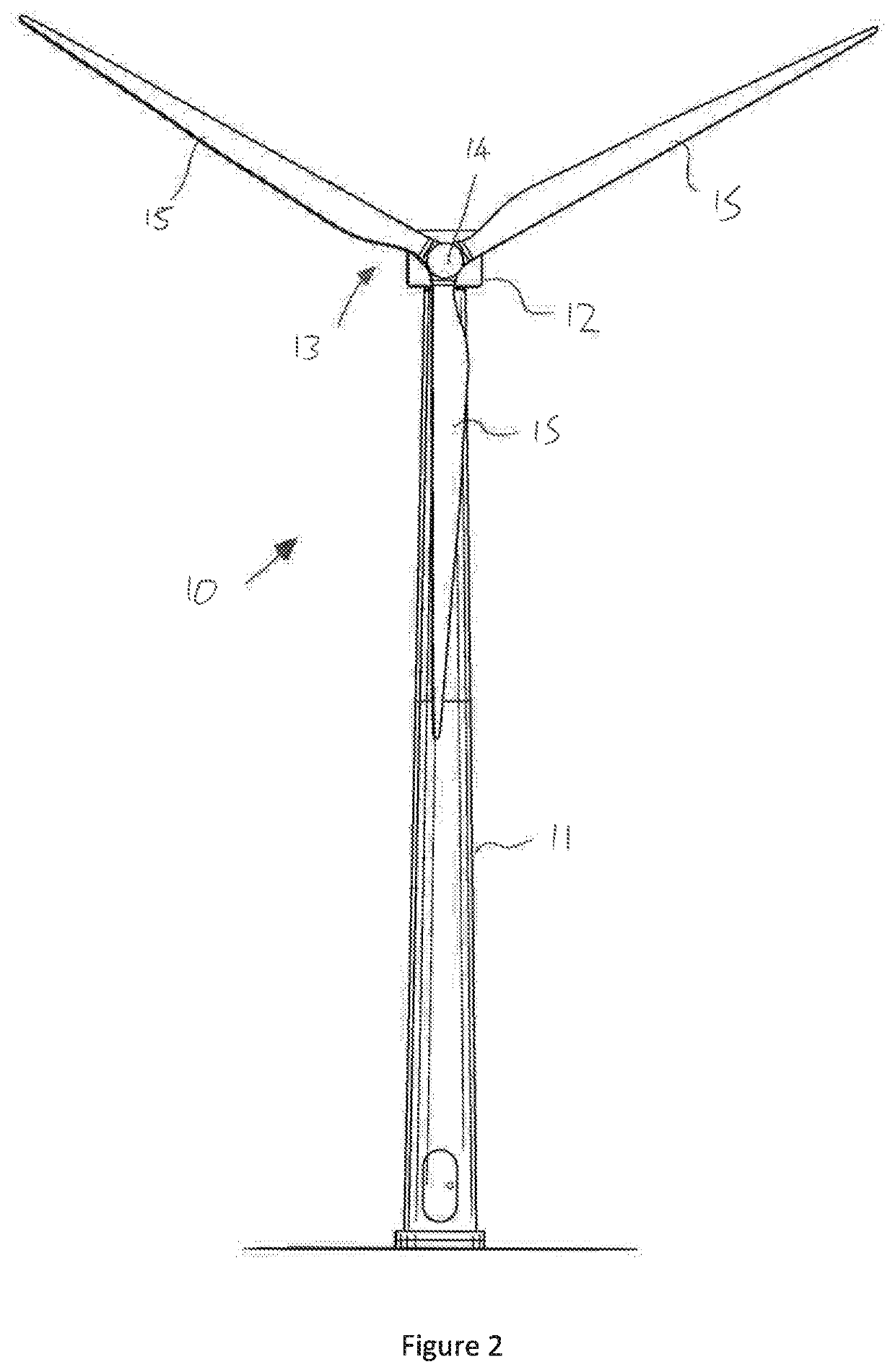
[0035]The HPP 1 comprises a plurality of wind turbine generators (WTGs) 10 and a plurality of segment 51 of PV modules 50. Each of the WTGs 10 and PV modules 50 is connected to a local grid 2 of the HPP 1 and configured to generate active power to be supplied via the local grid 2 to the main grid 100 for distribution. The local grid 2 is connected to the main grid 100 at a point of interconnection (Pol) 4 via a main step-up transformer 5 and a Pol bus 6.

[0036]For simplicity, FIG. 1 only illustrates a single WTG 10 and a single PV segment 51, both of which are connected to a single collector bus 3 of the loca...


PUM


Abstract

The present disclosure relates to a method of controlling operation of wind turbine generators (WTGs) in a hybrid power plant including both WTGs and PV modules. The method includes steps of: monitoring at least one operating parameter for one or more of the WTGs; monitoring at least one operating parameter for one or more of the PV modules; and controlling operation of the WTGs in dependence on the monitored operating parameters in order to control blade shadows cast by the WTGs on the PV modules and thereby optimise the power output of the PV modules, for example by reducing the blade shadow area cast on the PV modules.

Description

TECHNICAL FIELD[0001]The present disclosure relates to a method of operating a hybrid power plant comprising wind turbine generators (WTGs) and PV modules that are affected by blade shadows, in which the WTGs are controlled in order to optimise the power output of the PV modules.BACKGROUND[0002]Wind / solar hybrid power plants include a combination of wind turbine generators (WTGs) and PV modules that are configured to supply power to an external power transmission network or grid. By including both WTGs and PV modules in a single power plant it is possible to increase the amount of renewable energy that can be generated by the power plant, and provide more reliable power generation across a range of operating conditions. However, when PV modules are located close to WTGs in a hybrid power plant the PV modules may be affected by shadows cast by the WTGs, including static shadows cast by the WTG towers and moving or flickering shadows cast by the blades of the WTG rotors.[0003]WTG shad...

Claims


Application Information

Patent Timeline
Patent Type & Authority Applications(United States)
IPC IPC(8): H02S10/12F03D13/20F03D7/02F03D80/20
CPCH02S10/12F03D13/22F03D7/0204F05B2220/708F03D7/0264F03D80/20F03D7/0224F03D7/02F03D9/007H02S50/00H02J2300/24H02J2300/28H02J2300/40H02J3/004H02J3/381Y02E10/56Y02E10/76Y02E10/72Y04S10/50Y02E10/728
Inventor DEMSA, LORÁNDRAGHUCHANDRA, KARTHIKEYA BALLADIJENSEN, JACOB
Owner VESTAS WIND SYST AS
Why Eureka
Try Eureka