Method and device for controlling permanent magnet direct current brushless without hall motor

A control method, permanent magnet direct current technology, applied in the direction of electronically commutated motor control, single motor speed/torque control, control system, etc., can solve the problems of algorithm complexity, high cost of control chip, sensitive algorithm motor parameters, etc. Achieve improved power output, low cost, and good controllability

Active Publication Date: 2011-04-06
SINO WEALTH ELECTRONICS
View PDF3 Cites 10 Cited by
  • Summary
  • Abstract
  • Description
  • Claims
  • Application Information

AI Technical Summary

Problems solved by technology
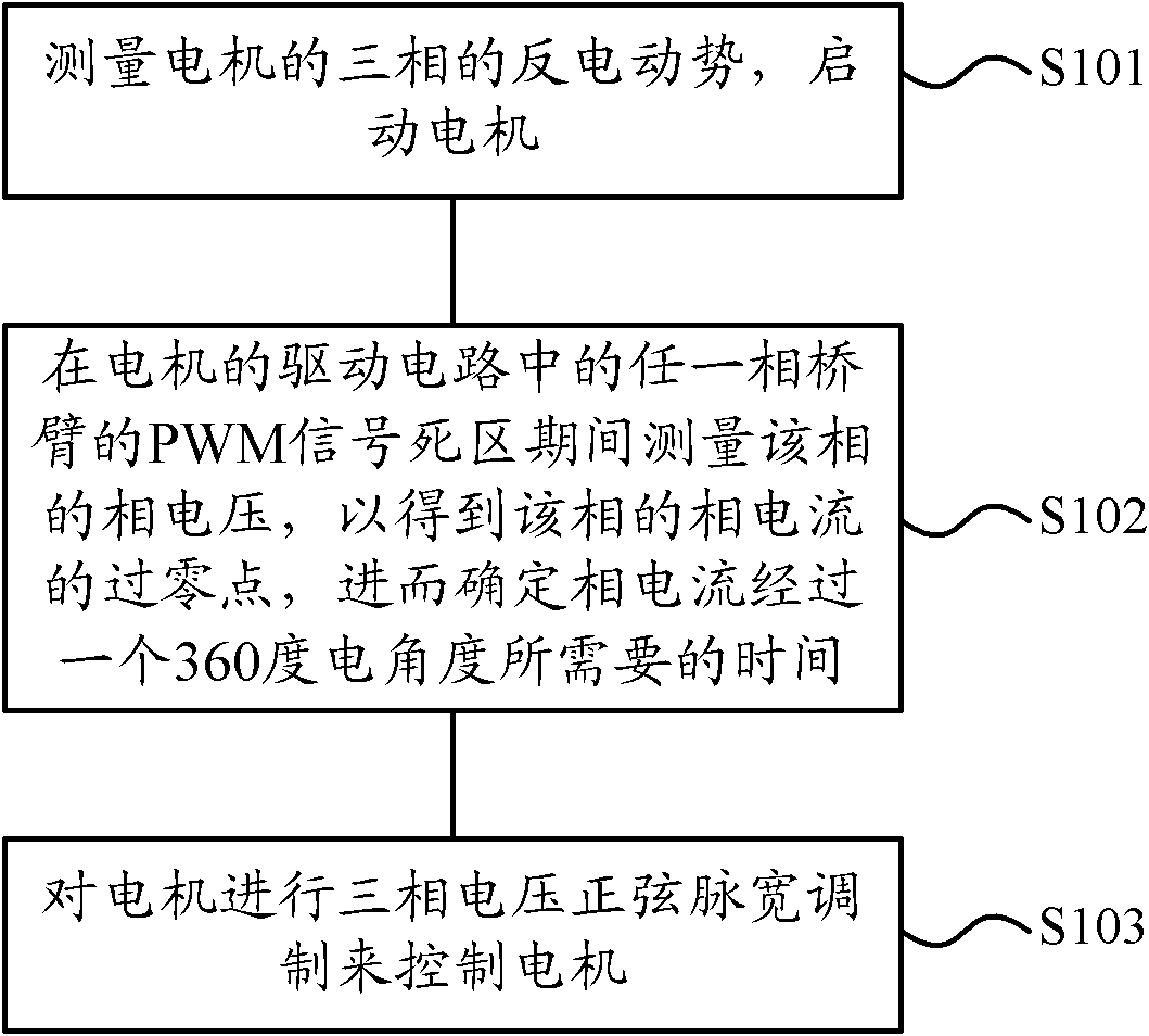
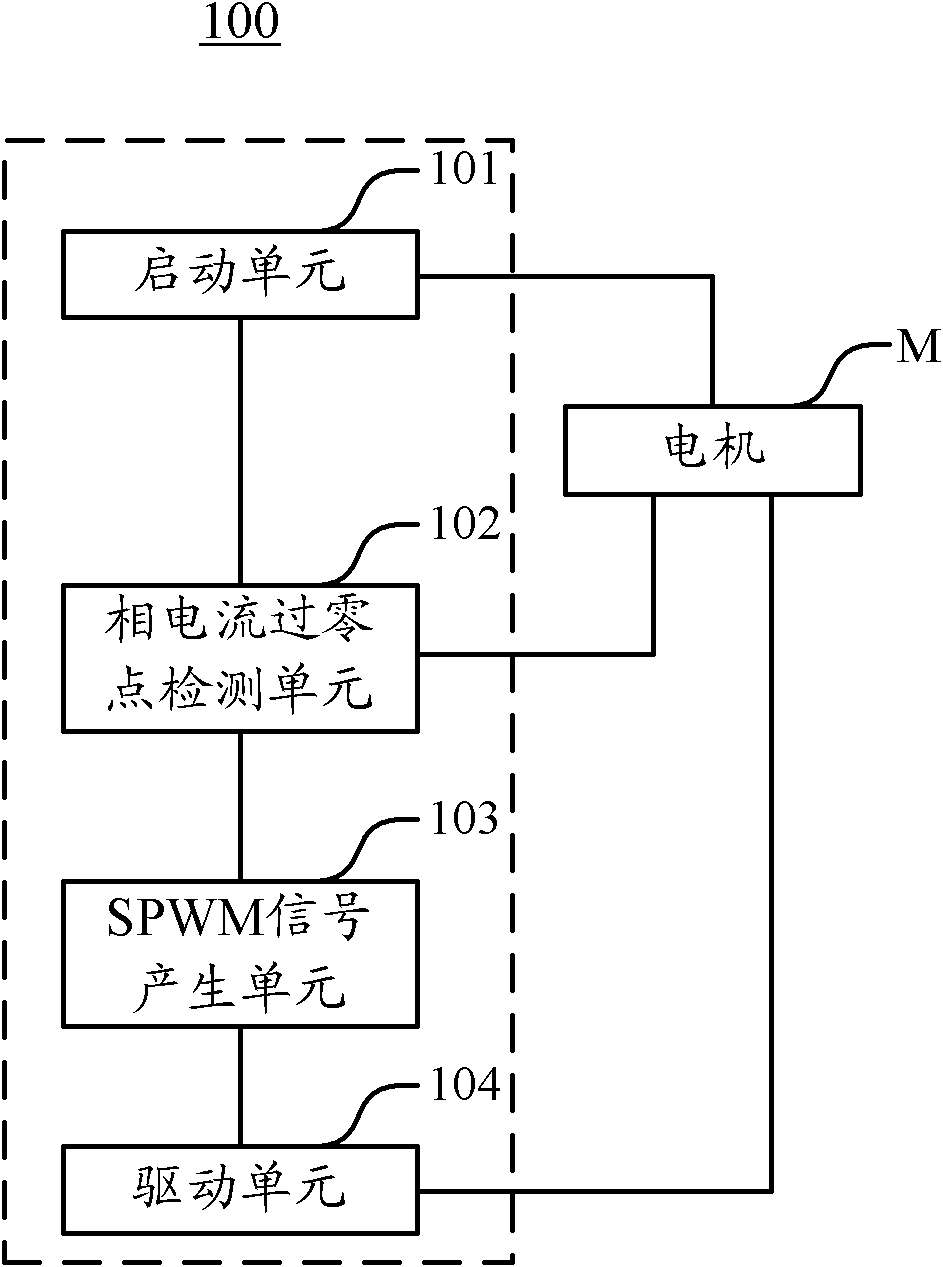
The disadvantage of the above method is that the cost of the control chip is too high due to the complexity of the algorithm, and the algorithm itself is sensitive to the parameters of the motor, so that the above method cannot control the operation of the motor well as expected

Method used


Image

  • Method and device for controlling permanent magnet direct current brushless without hall motor
  • Method and device for controlling permanent magnet direct current brushless without hall motor
  • Method and device for controlling permanent magnet direct current brushless without hall motor

Examples


Embodiment Construction

[0030] The present invention will be further described below in conjunction with specific embodiments and accompanying drawings, but the protection scope of the present invention should not be limited thereby.

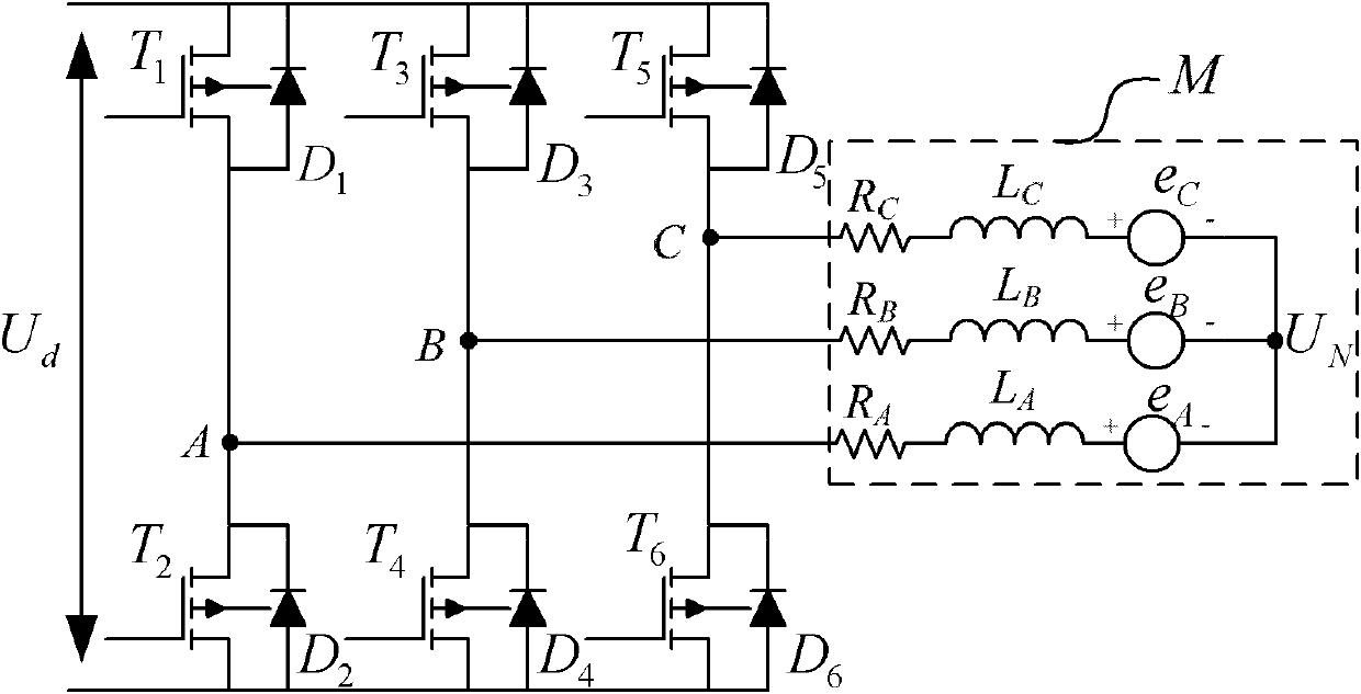
[0031] Before starting to describe the specific embodiments of the present invention, in order to facilitate the understanding of the present invention, first look at the equivalent schematic diagram of the permanent magnet DC brushless Hallless motor and its main driving circuit in the present invention. Such as figure 1 As shown, in an ideal case, the motor M can be equivalent to a structure composed of three stator windings A, B, and C, where the A-phase stator winding can include a resistor R connected in series A , inductance L A and the back electromotive force e to the midpoint of the stator winding A , similarly the phase B stator winding may consist of series connected resistors R B , inductance L B and the back electromotive force e to the midpoint of the...


PUM


Abstract

The invention provides a method for controlling a permanent magnet direct current brushless without hall motor, comprising the following steps of: measuring a three-phase counter electromotive force of the motor and starting the motor; measuring a phase voltage of any phase in a PWM (Pulse Width Modulation) signal dead zone period of the one phase of bridge arm in a driving circuit of the motor so as to obtain a zero crossing point of phase current of the phase to further determine the time required when the phase current passes through a 360-degree electrical angle; and carrying out three-phase voltage sine pulse width modification (SPWM) on the motor so as to control the motor. Correspondingly, the invention also provides a device for controlling the permanent magnet direct current brushless without hall motor. After the motor is started, the phase voltage of any phase is measured at the PWM signal dead zone period of the one phase of the bridge arm of the driving circuit of the motor to finally obtain the time required when the phase current passes through the 360-degree electrical angle, and then the motor is controlled by using a three-phase SPWM method. In the invention, the motor is controlled on the basis of the existing conditions without extra hardware resources; and the invention is simple and reliable and has good controllability and low cost.

Description

technical field [0001] The present invention relates to the technical field of permanent magnet DC brushless Hallless motors, in particular, the present invention relates to a control method and control device for permanent magnet DC brushless Hallless motors. Background technique [0002] After the permanent magnet DC brushless Hallless motor is started, it needs to continue to be controlled. The existing permanent magnet DC brushless Hallless motor control methods mainly include: [0003] (1) 180-degree control algorithm with low-cost MCU as the controller. The disadvantage of the above method is the need to switch Hall sensors, resulting in increased operating costs for the entire motor system. In addition, the reliability of the motor system depends on the reliability of the Hall sensor itself, so that the reliability of the motor system cannot be guaranteed. [0004] (2) The vector control method of permanent magnet rotor flux orientation is adopted. The disadvantag...

Claims


Application Information

Patent Timeline
Patent Type & Authority Applications(China)
IPC IPC(8): H02P6/08H02P6/18H02P6/182
Inventor 陈朝辉周序伟辛巍尹志光
Owner SINO WEALTH ELECTRONICS
Why Eureka
Try Eureka