

High-beam-quality high-power output combining device of semiconductor laser
A semiconductor and high-beam technology, applied in the direction of semiconductor laser optical devices, semiconductor lasers, lasers, etc., can solve the problems that cannot be superimposed infinitely, generally no more than 50 layers, it is difficult to directly apply light sources, and the quality of output beams deteriorates, etc., to achieve Good beam quality level, achieve high power and high beam quality, and improve the effect of output power
- Summary
- Abstract
- Description
- Claims
- Application Information
AI Technical Summary
Problems solved by technology
Method used
Image

Examples
Embodiment 1
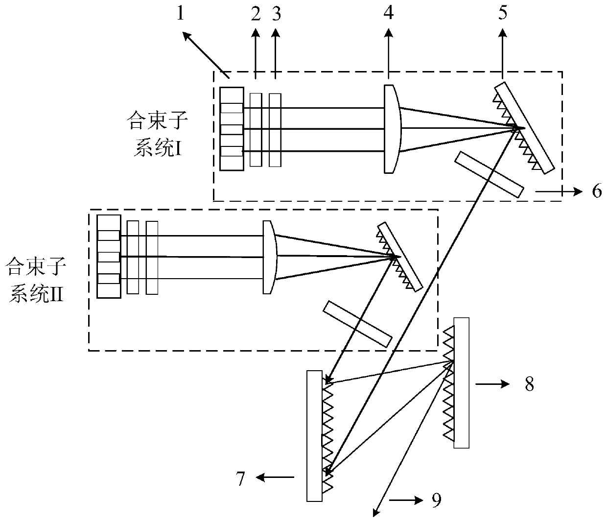
[0032] refer to figure 1 , in this embodiment, the beam combining device with high beam quality and high power output of semiconductor lasers includes two beam combining subsystems: beam combining subsystem I and beam combining subsystem II with the same structure, and the output sub-beams of the two beam combining subsystems are directly incident onto the second grating 7. The sub-beams output by the output mirror 6 of the beam combining subsystem I and the sub-beams output by the output mirror 6 of the beam combining subsystem II are both directly incident on the second grating 7 in the grating pair. In order to obtain higher diffraction efficiency of the sub-beam, the incident angle of the sub-beam should be as close as possible to the Littrow angle of the second grating 7 at the blaze wavelength. The second grating 7 and the third grating 8 are placed in parallel, and the third grating 8 will effectively compensate the dispersion generated by the second grating 7 . The d...
Embodiment 2
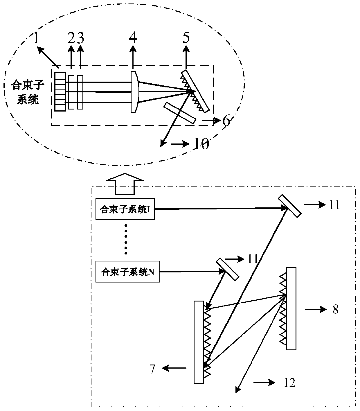
[0035] refer to figure 2, in this embodiment, the number N of beam combining subsystems is greater than 2 (the structures of the N beam combining subsystems are all the same, and are also the same as in the above-mentioned embodiments, as shown in the dotted ellipse frame), and the semiconductor laser has high beam quality The high-power output beam combining device also includes N mirrors 11, and the N mirrors 11 correspond to the N beam combining subsystems one by one, and are used to reflect the output sub-beam 10 of each beam combining subsystem to the second grating 7 . That is, the sub-beams 10 output by each beam combining subsystem are reflected to the second grating 7 by a mirror 11, and the dispersion of the second grating 7 makes the first-order diffracted beams of the sub-beams 10 of different wavelengths incident on the third third grating with the same parameters. Overlap occurs at the same position of the grating 8, and after diffraction by the third grating 8...
PUM
| Property | Measurement | Unit |
|---|---|---|
| Wavelength | aaaaa | aaaaa |
Abstract
Description
Claims
Application Information