Radiographic phase-contrast imaging apparatus

a phase-contrast imaging and phase-contrast technology, applied in the direction of instruments, patient positioning for diagnostics, applications, etc., can solve the problems of affecting the correct derivation of the positional relationship between the subject and the imaging system may be changed, and the difficulty in accurately deriving the phase variation of the x-ray generated, etc., to achieve the effect of high precision, increased cost and high precision

Inactive Publication Date: 2014-07-15
FUJIFILM CORP
View PDF16 Cites 49 Cited by
  • Summary
  • Abstract
  • Description
  • Claims
  • Application Information

AI Technical Summary

Benefits of technology

[0010]With the radiographic phase-contrast imaging apparatus disclosed in Patent Documents 1 and 2, however, it is necessary to move the first or second grating at a pitch that is smaller than the grating pitch thereof with precision. The grating pitch is typically several micrometers, and even higher precision is required for the translation of the grating. This requires an extremely high precision moving mechanism, resulting in a complicated mechanism and increased costs. Further, there is a problem that, when an imaging operation is performed each time the grating is translated, a positional relationship between the subject and the imaging system may be changed due to motion of the subject and / or vibration of the apparatus during a series of imaging operations for obtaining a phase-contrast image. This hinders correctly deriving the phase variation of the X-ray generated by interaction with the subject, and hinders obtaining a good phase-contrast image, as a result.
[0011]In view of the above-described circumstances, the present invention is directed to providing a radiographic phase-contrast imaging apparatus that allows obtaining a good phase-contrast image by a single imaging operation without requiring a high precision moving mechanism.

Problems solved by technology

This requires an extremely high precision moving mechanism, resulting in a complicated mechanism and increased costs.
Further, there is a problem that, when an imaging operation is performed each time the grating is translated, a positional relationship between the subject and the imaging system may be changed due to motion of the subject and / or vibration of the apparatus during a series of imaging operations for obtaining a phase-contrast image.
This hinders correctly deriving the phase variation of the X-ray generated by interaction with the subject, and hinders obtaining a good phase-contrast image, as a result.

Method used


Image

  • Radiographic phase-contrast imaging apparatus
  • Radiographic phase-contrast imaging apparatus
  • Radiographic phase-contrast imaging apparatus

Examples


first embodiment

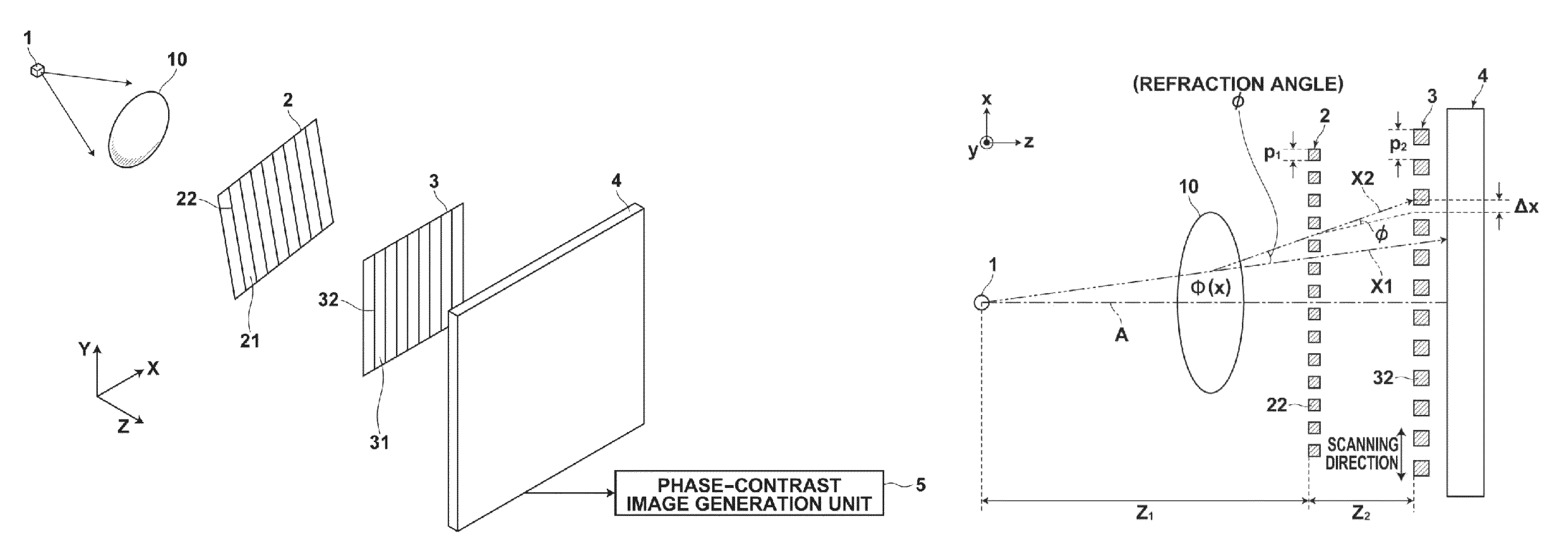
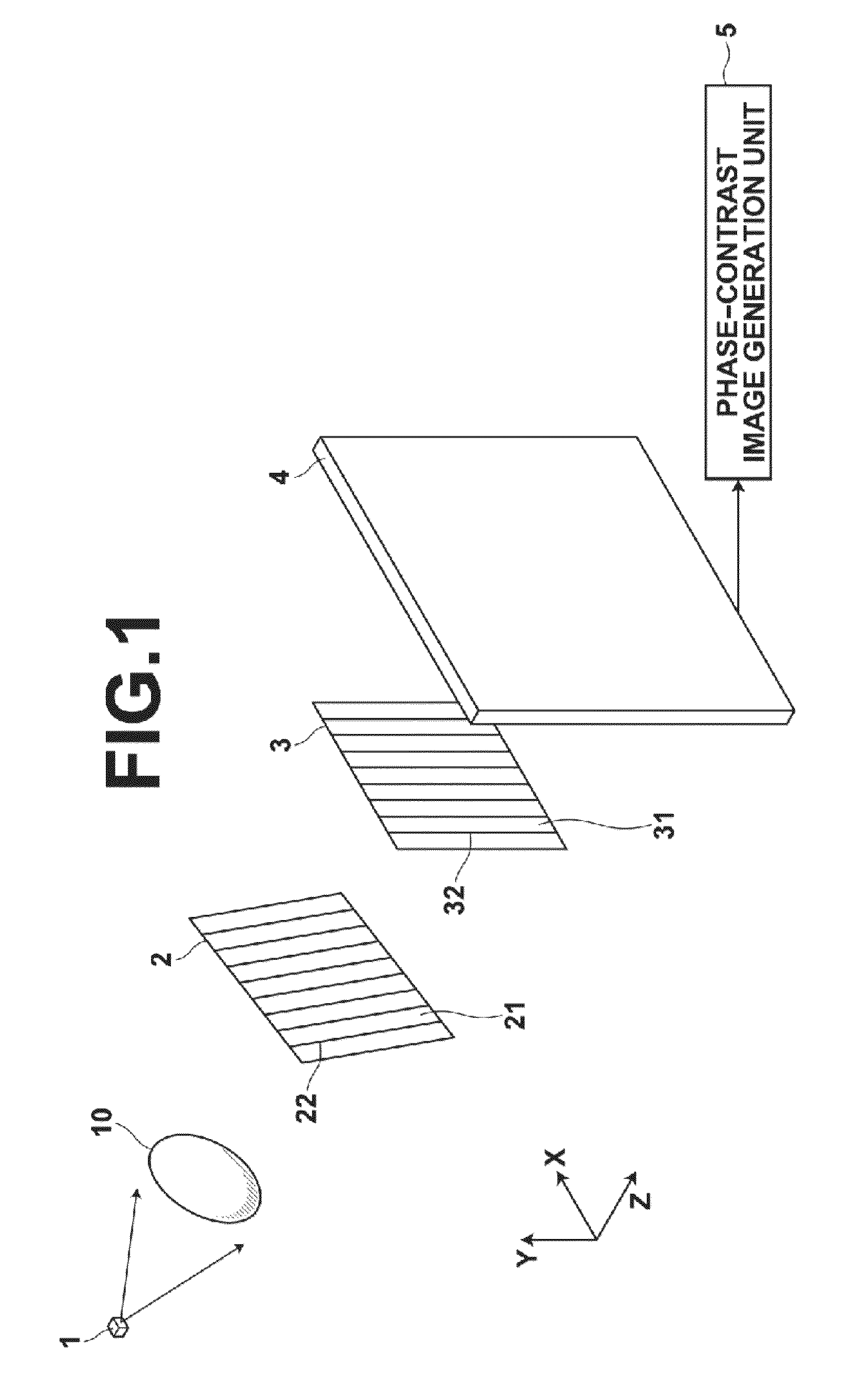
[0179]Further, although the direction in which the second grating 3 extends is parallel to the Y-direction and the direction in which the self image G1 of the first grating 2 extends is inclined relative to the Y-direction by θ, as shown in FIG. 6, in the above-described first embodiment, the direction in which the self image G1 of the first grating 2 extends may be parallel to the Y-direction, and the direction in which the second grating 3 extends may be inclined relative to the Y-direction by θ.

[0180]Still further, the relative angle of rotation θ in the X-Y plane between the self image G1 of the first grating 2 and the second grating 3 may be expressed by Expression (21) below, in place of Expression (13), based on a relationship between a sub-pixel size Dsub and a period T of the moire pattern formed by the self image G1 of the first grating 2 and the second grating 3. In Expression (21) below, Z1 is a distance from the focal spot of the radiation source 1 to the first grating ...

second embodiment

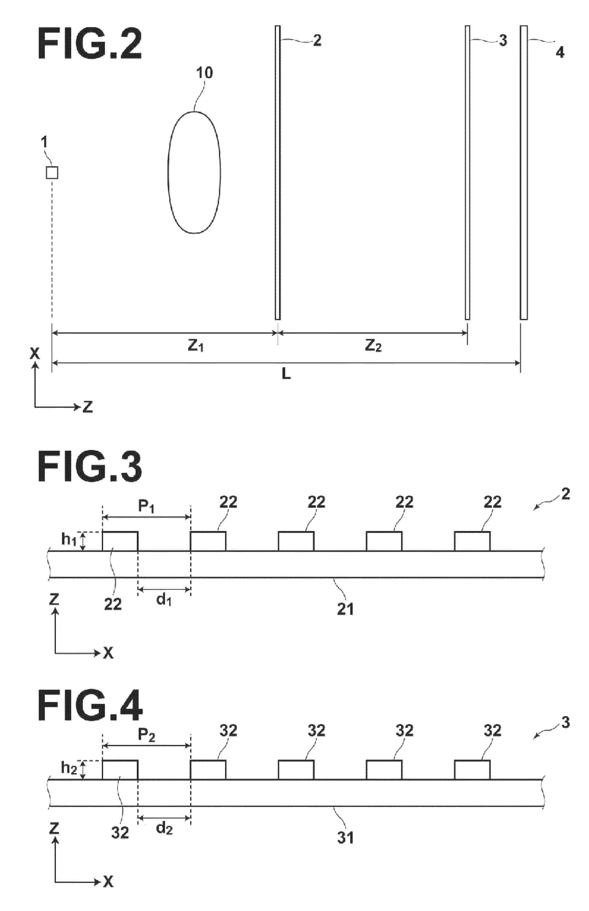
[0188]Specifically, in the radiographic phase-contrast imaging apparatus of the second embodiment, both the first grating 2 and the second grating 3 are formed as absorption type (amplitude modulation type) gratings, and are adapted to geometrically project the radiation passed through the slits irrespectively of the Talbot interference effect. In more detail, values of the interval d1 of the first grating 2 and the interval d2 of the second grating 3 are set to be sufficiently greater than the effective wavelength of the radiation applied from the radiation source 1, so that the most part of the applied radiation forms the self image G1 of the first grating 2 behind the first grating 2 without being diffracted by the slits. For example, in the case where tungsten is used as the target of the radiation source and the tube voltage is 50 kV, the effective wavelength of the radiation is about 0.4 Å. In this case, by setting the interval d1 of the first grating 2 and the interval d2 of ...


PUM

PropertyMeasurementUnit
angleaaaaaaaaaa
energyaaaaaaaaaa
thickness h1aaaaaaaaaa

Abstract

A radiographic phase-contrast imaging apparatus obtains a phase-contrast image using two gratings including the first grating and the second grating. The first and second gratings are adapted to form a moire pattern when a periodic pattern image formed by the first grating is superimposed on the second grating. Based on the moire pattern detected by the radiographic image detector, image signals of the fringe images, which correspond to pixel groups located at different positions with respect to a predetermined direction, are obtained by obtaining image signals of pixels of each pixel group, which includes pixels arranged at predetermined intervals in the predetermined direction, as the image signal of each fringe image, where the predetermined direction is a direction parallel to or intersecting a period direction of the moire pattern other than a direction orthogonal to the period direction. Then, a phase-contrast image is generated based on the obtained fringe images.

Description

BACKGROUND OF THE INVENTION[0001]1. Field of the Invention[0002]The present invention relates to a radiographic phase-contrast imaging apparatus using gratings.[0003]2. Description of the Related Art[0004]X-rays have a nature that they attenuate depending on the atomic number of an element forming a substance and the density and thickness of the substance. Because of this nature, X-rays are used as a probe to investigate the interior of a subject. Imaging systems using X-rays have widely been used in the fields of medical diagnosis, nondestructive testing, etc.[0005]With a typical X-ray imaging system, a subject is placed between an X-ray source, which emits an X-ray, and an X-ray image detector, which detects an X-ray image, to take a transmission image of the subject. In this case, each X-ray emitted from the X-ray source toward the X-ray image detector attenuates (is absorbed) by an amount depending on differences of characteristics (such as the atomic number, density and thickne...

Claims


Application Information

Patent Timeline
Patent Type & Authority Patents(United States)
IPC IPC(8): A61B6/00G01N23/04
CPCA61B6/484A61B6/4464G01N2223/612A61B6/4291G01N2223/419G21K2207/005A61B6/502G01N23/046A61B6/4233G01T1/246G01N23/041
Inventor MURAKOSHI, DAIAGANO, TOSHITAKAITO, WATARUIMAI, SHINJI
Owner FUJIFILM CORP
Why Eureka
Try Eureka