Method for bending and thermally prestressing radiation shielding glass

a radiation shielding glass and thermal prestressing technology, applied in glass tempering apparatus, glass making apparatus, glass shaping apparatus, etc., can solve the problems of reduced mechanical and chemical stability or strength of the surface, 2- or 3-dimensional deformation of such glasses, and inability to thermal prestress such glasses by known bending methods, etc., to achieve high quality

Active Publication Date: 2014-07-22
SCHOTT AG
View PDF31 Cites 9 Cited by
  • Summary
  • Abstract
  • Description
  • Claims
  • Application Information

AI Technical Summary

Benefits of technology

[0012]It is a first object of the invention to disclose a method for bending radiation shielding glass, by means of which reliable bending of the glass into a desired 2-dimensional or 3-dimensional shape with high quality is ensured.
[0013]It is a second object of the invention to disclose a method for bending radiation shielding glass which avoids the danger of damage to the glass.

Problems solved by technology

Such glasses moreover have reduced mechanical and chemical stability or strength of the surfaces compared with conventional soda-lime glasses.
A 2- or 3-dimensional deformation of such glasses and also thermal prestressing of such glasses are not possible by known bending methods (cf. for example U.S. Pat. No. 5,372,624).

Method used


Image

  • Method for bending and thermally prestressing radiation shielding glass
  • Method for bending and thermally prestressing radiation shielding glass
  • Method for bending and thermally prestressing radiation shielding glass

Examples


example 1

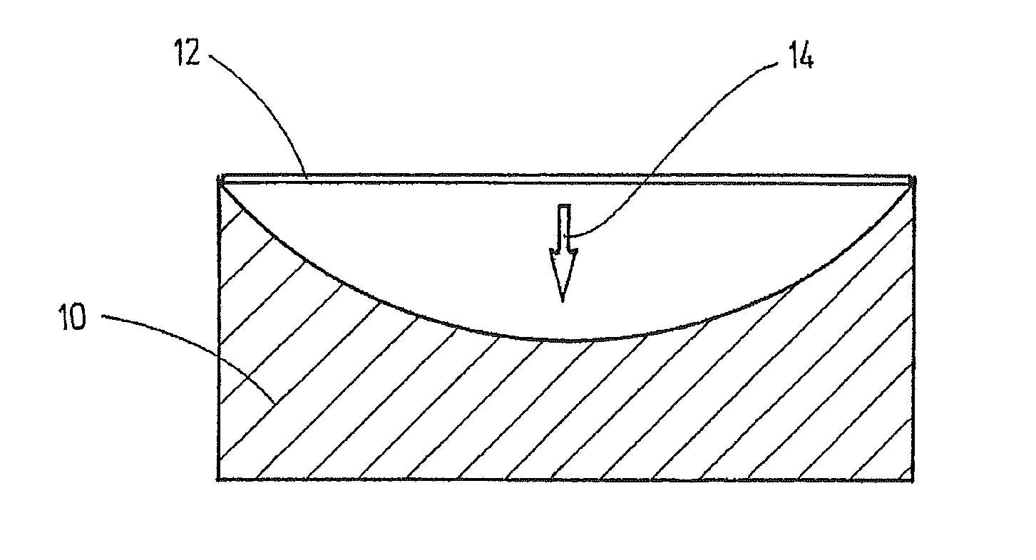
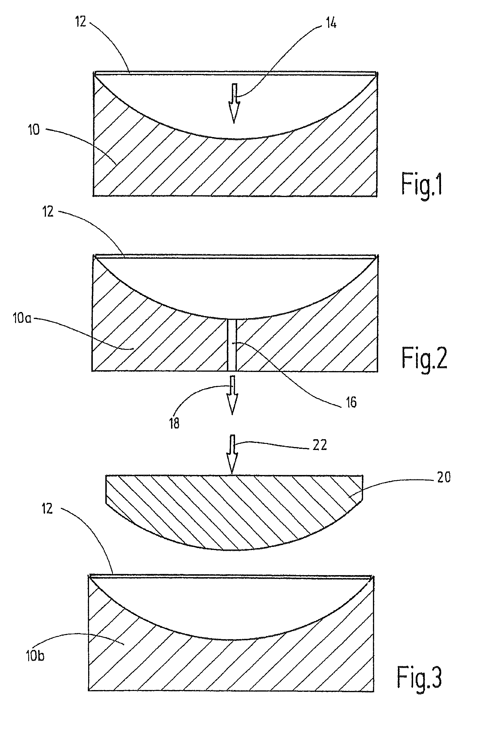
[0071]The mold 10 is first treated with a release agent, for example with graphite powder, and then preheated in a furnace, initially to 350 to 400° C. Thereafter, a cold glass plate was placed on top. Further heating in the furnace was then effected to 400° C. over a period of 60 minutes and finally heating to about 480° C. over a period of 30 minutes. Gravitational molding, as shown in FIG. 1, took place during this procedure. This was followed by cooling in the mold 10 with the following temperature program: cooling to 400° C. over 60 minutes, further cooling to 300° C. over 70 minutes, further cooling to 200° C. over 60 minutes, further cooling to 150° C. over 20 minutes, finally cooling to 70° C. over 30 minutes. The molded glass body was then removed.

example 2

[0072]The same data as in Example 1 were used. However, as shown schematically in FIG. 2, the vacuum was additionally employed as an aid. The mold 10a was subjected to a reduced pressure of about 70 kPa.

example 3

[0073]As in Examples 1 and 2, a glass plate measuring 500×800 mm×thickness of 6 mm comprising the radiation shielding glass RD 50® was used. The mold 10b was produced in the same manner as described above and pretreated by applying a release agent (graphite powder). A double pressing process according to FIG. 3 was then used.

[0074]For this purpose, the mold was first preheated in the furnace to about 350 to 400° C., the cold glass plate was placed on top and brief heating was then effected again in the furnace to about 400 to 450° C. Thereafter, the mold 10b with the glass plate 12 placed on top was transported out of the furnace and a male mold 20 consisting of an aluminum alloy and covered with a woven glass filament fabric was gradually moved downwards up to a maximum pressure of about 6 bars by a pneumatic cylinder in order to press the glass plate 12 against the inner surface of the mold 10b. The pressing process lasted for about 4 to 5 seconds. The male mold was then immediate...


PUM

PropertyMeasurementUnit
temperatureaaaaaaaaaa

Abstract

A method for bending radiation shielding glass which has a heavy metal oxide content of at least 50% by weight is provided, wherein first a mold is provided, a glass plate comprising a radiation shielding glass is then provided, the mold is preheated to a temperature of 300 to 400° C., the glass plate is placed on the mold, the glass plate and the mold are heated in a furnace to a temperature of 370 to 430° C., then heated together to a temperature of 400° C. to 500° C., preferably to 440 to 500° C., the total heating time being at least 30 minutes, preferably at least 60 minutes, the glass plate is then molded and finally the molded glass is cooled by means of a cooling program over a period of at least 60 minutes. For thermal prestressing, the glass body is supported at least at its outer periphery at a number of support points, introduced into a preheated furnace, heated to 400 to 500° C. and then removed, and cold air is blown onto both sides from a multiplicity of nozzles, preferably until cooling to about 100° C. has taken place.

Description

CROSS REFERENCES TO RELATED APPLICATIONS[0001]This application claims priority from German patent application 10 2009 036 164.2, filed on Jul. 28, 2009, and from German patent application 10 2009 024 234.1 filed on May 28, 2009. The entire contents of these priority applications are incorporated herein by reference.BACKGROUND OF THE INVENTION[0002]The invention relates to a method for bending radiation shielding glass and a method for thermally prestressing a radiation shielding glass or a glass body consisting thereof.[0003]Within the scope of this application, a “radiation shielding glass” is understood as meaning a glass which meets the requirements for lead glass panes according to the German and European standards DIN EN 61331-1 (August 2006 version) and DIN EN 61331-2 (April 2002 version), i.e. the attenuation equivalent in mm Pb must not be less than 0.22 times the minimum permitted lead glass plane in millimeters. The above standards are based on the international standard I...

Claims


Application Information

Patent Timeline
Patent Type & Authority Patents(United States)
IPC IPC(8): C03B27/044C22C38/22C03B23/03C03B40/00C03B23/035C03B27/04C03B23/025
CPCC03B23/0252C03B27/0413C03B40/005C03B27/0445C03B23/0302C03B23/0357C22C38/22Y10T428/24628C03C3/07
Inventor SCHILLERT, HORSTROESSLER, DIRKMEVERS, DETLEF
Owner SCHOTT AG
Why Eureka
Try Eureka