
Signal processing apparatus, ultrasonic apparatus, control method for signal processing apparatus, and control method for ultrasonic apparatus

a signal processing and ultrasonic technology, applied in the direction of instruments, specific gravity measurements, applications, etc., can solve the problems of difficult to generate acoustic shadows, difficult to extract high reflectors, and difficult to generate shadows, etc., to achieve small detection signals and improve the resolution of an entire image

Active Publication Date: 2014-07-22
CANON KK
View PDF14 Cites 7 Cited by
  • Summary
  • Abstract
  • Description
  • Claims
  • Application Information

AI Technical Summary

Benefits of technology

The present invention provides a technique for detecting the position, size, and shape of a unique region in received waveform data of ultrasonic waves. This technique can assist in the detection of a unique region, such as a high reflector, and can estimate its physical property values with high precision. The invention can also detect other physical characteristics of the unique region, such as its size and shape. This can be useful in ultrasonic diagnostics and other fields where the detection and characterization of unique regions is important.

Problems solved by technology

However, the above-mentioned acoustic shadow can not sometimes be generated easily depending on the position, the size, and the shape of the high reflector, and in that case, the extraction of the high reflector becomes difficult.
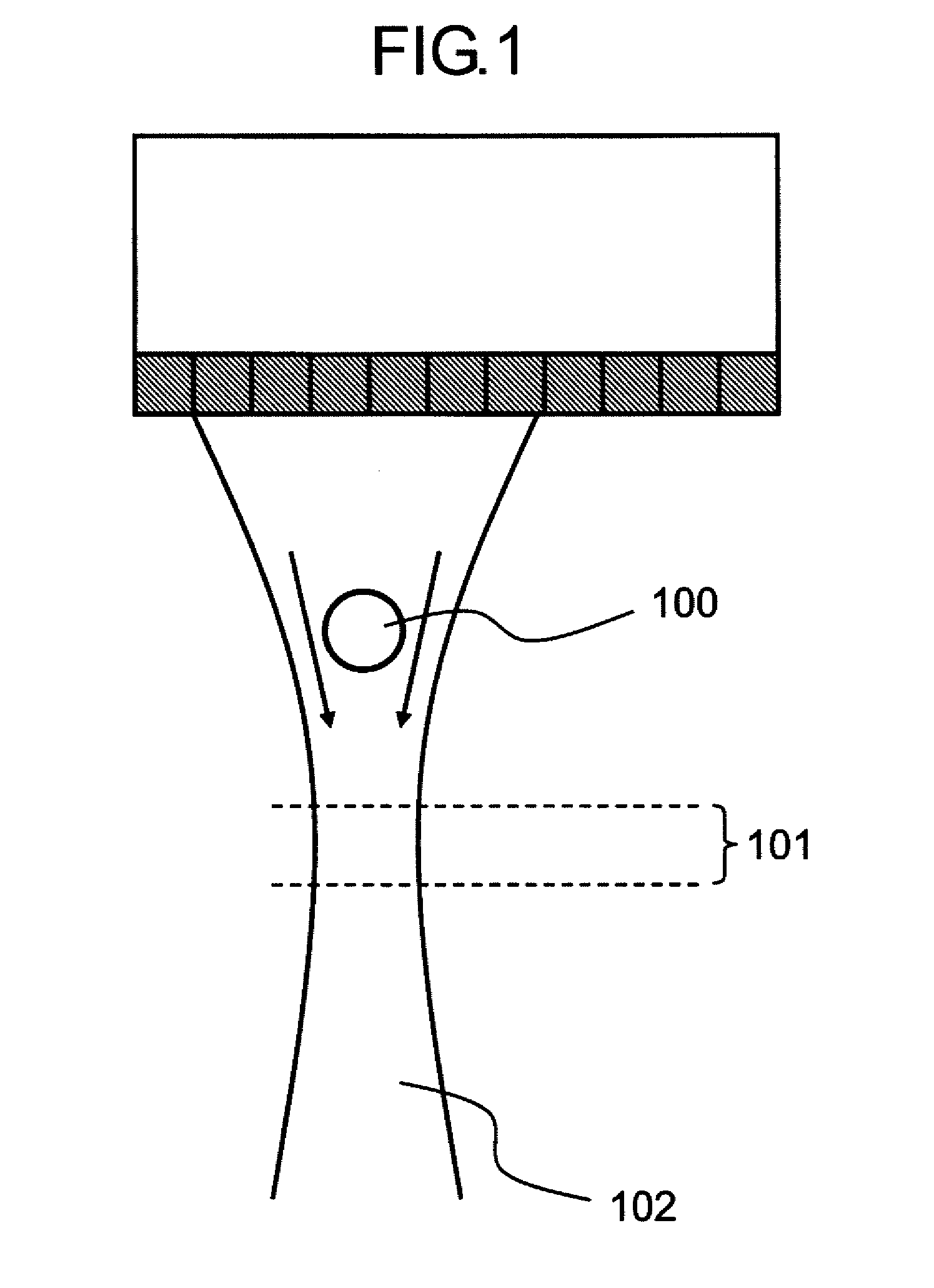
Therefore, it becomes difficult to generate an acoustic shadow due to the high reflector 100, and a search for the acoustic shadow becomes difficult.
That is, even with a high reflector, a small detection signal may result.
However, a lot of information may be lost from the ultrasonic signals in such processes.
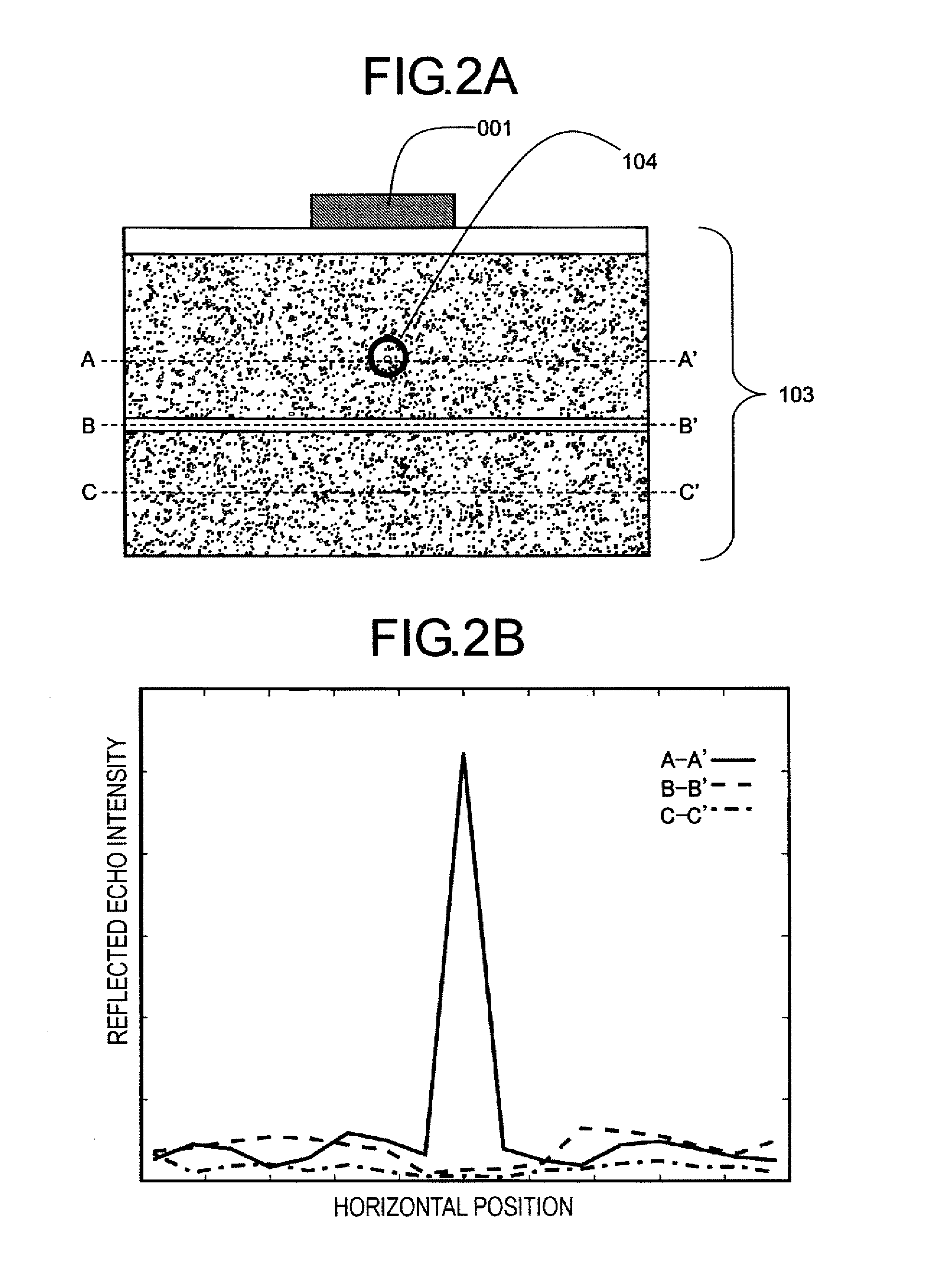
Thus, it is difficult to determine based solely on the intensities of reflected echoes whether a high reflector exists.
Further, in case where a speckle pattern is generated by the interference of reflected echoes from a minute scatterer and the reflected echoes of a high reflector exist together therein, it is difficult to extract those signals which originate only in the minute scatterer in a selective manner, and to discriminate them from other signals.
In particular, in case where the high reflector is small and appears as a point-like echo on an image, it becomes more difficult to discriminate the high reflector.
Therefore, it is difficult to extract the high reflector by applying the technique described in Japanese patent application laid-open No.

Method used


Image

  • Signal processing apparatus, ultrasonic apparatus, control method for signal processing apparatus, and control method for ultrasonic apparatus
  • Signal processing apparatus, ultrasonic apparatus, control method for signal processing apparatus, and control method for ultrasonic apparatus
  • Signal processing apparatus, ultrasonic apparatus, control method for signal processing apparatus, and control method for ultrasonic apparatus

Examples


first embodiment

[0066]Hereinafter, in a first embodiment, description will be given to a supersonic apparatus that calculates a cross-correlation of adjacent scan lines and indicates position information in which the correlation becomes equal to or less than a set value.

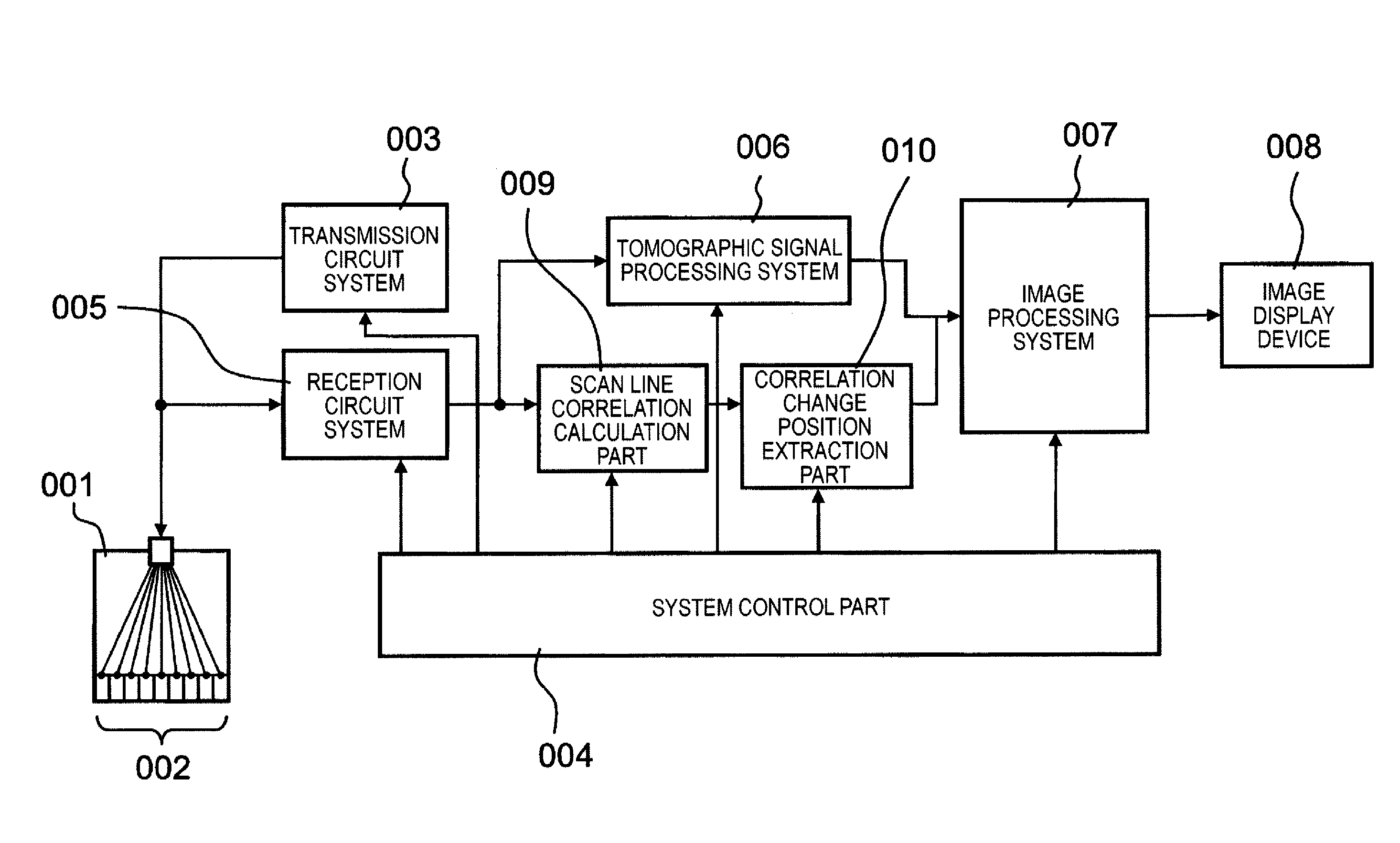
[0067]FIG. 4 is a system schematic diagram showing the ultrasonic apparatus according to the first embodiment of the present invention. This ultrasonic apparatus has a function to generate and display an ordinary ultrasonic tomographic image, and a function to detect a high reflector in a living body and to display candidates for the existence position thereof (a scan line correlation calculation part 009 and a correlation change position extraction part 010). For instance, the latter function is used for the detection of a calculus, a minute calcification region, etc.

(Generation and Display of Tomographic Image)

[0068]First of all, a flow until a tomographic image is displayed will be described by using FIG. 4. The ultrasonic appara...

second embodiment

[0090]Hereafter, in a second embodiment, reference will be made to an example of a case in which not only the cross-correlation between adjacent scan lines but also the intensity thereof is used for detecting the position of a high reflector.

[0091]FIG. 9 is a system schematic diagram showing an ultrasonic apparatus according to this embodiment. The flow of signals displaying a tomographic image is the same as that of the first embodiment, and hence is omitted.

[0092]A reception circuit system 005 outputs received waveform data. A scan line correlation calculation part 009 calculates a cross-correlation between adjacent scan lines from the received waveform data input thereto. The scan line correlation calculation part 009 outputs the cross-correlation, and a correlation change position extraction part 010 extracts a position at which the correlation value changes as a first candidate for the existence position of a high reflector. Then, in order to acquire the intensity of an echo in...

third embodiment

[0094]Hereafter, in a third embodiment, reference will be made to an ultrasonic apparatus that calculates a cross-correlation value from the received waveform data of adjacent scan lines, extracts an existence position candidate for a high reflector, and further estimates the physical property values of the high reflector from an intensity ratio of adjacent scan lines.

[0095]FIG. 10A is a system schematic diagram showing the ultrasonic apparatus according to this embodiment. FIG. 10B is a view showing the construction of a hatched region in FIG. 10A in detail. The processing of displaying a tomographic image is similar to that in the above-mentioned embodiments. A scan line correlation calculation part 021 outputs the cross-correlation of the received waveform data of adjacent scan lines. A correlation change position extraction part 023 detects a position at which the correlation value becomes equal to or less than a set value, and transmits the position information thus obtained to...


PUM


Abstract

A signal processing apparatus scans a beam of elastic waves into an object to be examined, acquires received waveform data of a plurality of scan lines, and performs signal processing to form a tomographic image of said object to be examined from the received waveform data of the plurality of scan lines. The signal processing apparatus includes a scan line correlation calculation part (009) that calculates a correlation value of received waveform data between a first scan line and a second scan line that has a prescribed correlation with the first scan line, for a plurality of positions on the scan lines, and a correlation change position extraction part (010) that extracts, from among the plurality of positions on said scan lines, a position at which the correlation value becomes a value different from a prescribed value as a position at which a unique region can exist.

Description

TECHNICAL FIELD[0001]The present invention relates to a signal processing apparatus and an ultrasonic apparatus that acquire a tomographic image or a three-dimensional image of a sample by using ultrasonic waves in the form of elastic waves, and in particular, it relates to a signal processing apparatus and an ultrasonic apparatus for detecting a unique region such as a reflector of high reflectivity, etc.[0002]Also, the present invention relates to a control method for a signal processing apparatus and a control method for an ultrasonic apparatus for acquiring a tomographic image or a three-dimensional image of a sample by using ultrasonic waves in the form of elastic waves, and in particular, it relates to a control method for a signal processing apparatus or a control method for an ultrasonic apparatus for detecting a unique region such as a reflector of high reflectivity, etc.BACKGROUND ART[0003]A conventional apparatus for obtaining a tomographic image by using ultrasonic waves...

Claims


Application Information

Patent Timeline
Patent Type & Authority Patents(United States)
IPC IPC(8): A61B8/00
CPCG01S7/52036A61B8/0825A61B8/0833G01S7/52073G01S15/8977
Inventor TAKI, HIROFUMINAGAE, KENICHISATO, TORU
Owner CANON KK
Learn More