Irradiation device having transition glass seal
a transition glass and irradiation device technology, applied in the direction of optical radiation measurement, electric discharge tube/lamp manufacture, spectrometry/spectrometry/monochromator, etc., can solve the problems of limiting the service life of infrared emitters and their output, complicated production, and disadvantages of pinched sections, etc., to achieve high and efficient energy application
- Summary
- Abstract
- Description
- Claims
- Application Information
AI Technical Summary
Benefits of technology
Problems solved by technology
Method used
Image
Examples
example 1
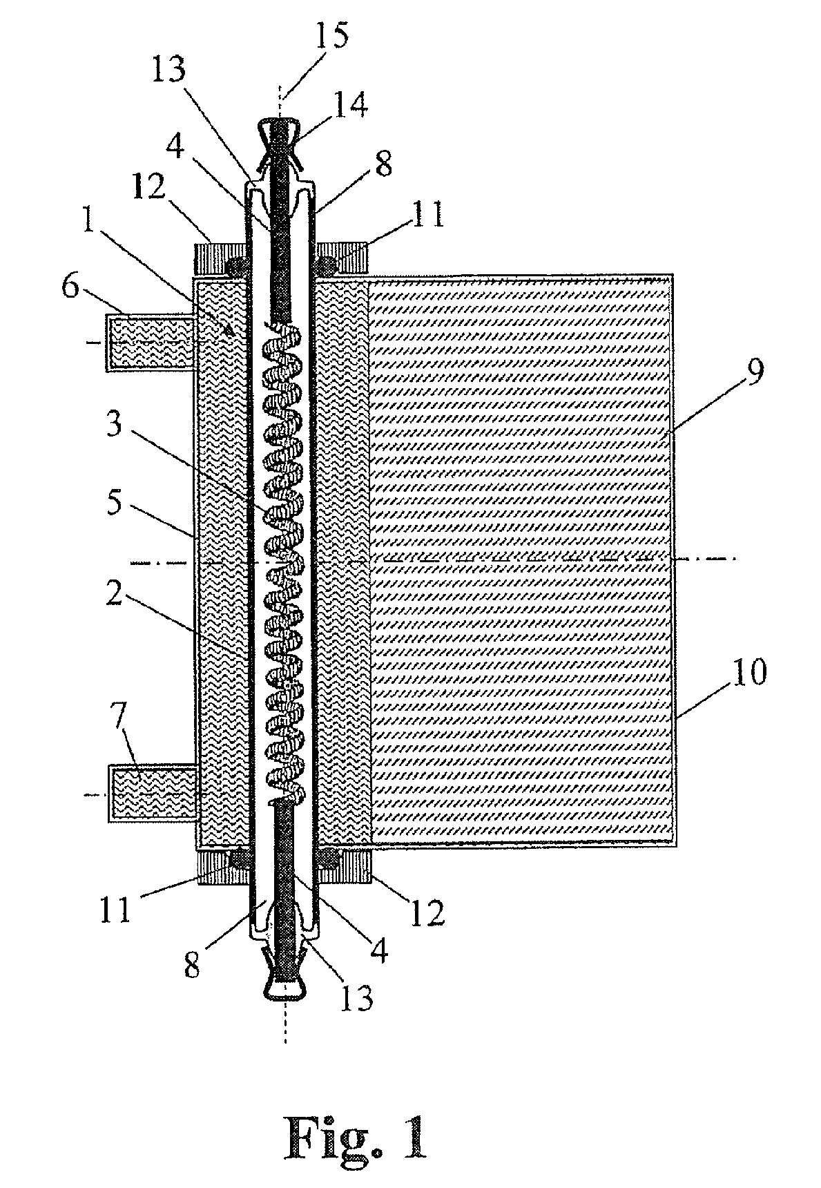
[0071]FIG. 1 shows schematically a handheld irradiation device for cosmetic purposes. It is equipped with an infrared emitter 1, wherein this involves a shortwave IR emitter having a nominal power of 250 W.
[0072]The infrared emitter 1 has an axially symmetrical emitter tube 2 made of quartz glass having a round cross section and an outer diameter of 10 mm and a length of 100 mm. The ends of the emitter tube 2 are not deformed and have the same cross section and diameter as the middle part of the emitter tube 2.
[0073]The emitter tube 2 encloses an interior chamber gas-tight, wherein a coil-shaped heating filament 3 made of tungsten having a (heated) length of 50 mm is arranged in this interior chamber and this interior chamber is filled with argon (without halogen additives). The ends of the heating coil 3 are each welded with a round electrical connection pin 4 having an outer diameter of 2 mm, also made of tungsten. The connection pins 4 are led out from opposing open end sides of ...
example 2
[0080]In general, there is only a limited space available for installations in the evacuated region. Indeed, bus bars can be placed in isolated or gas-filled, separate spaces. However, it is difficult to connect the emitters to these bus bars, such that no sparkovers are produced. The gaps of the seal must also be designed with very tight tolerances, in order to prevent the penetration of sparkovers or the formation of surface discharges.
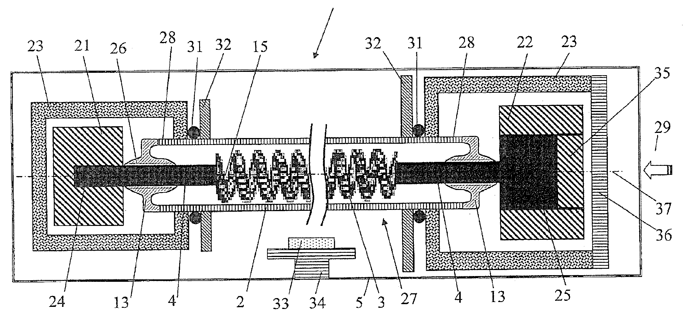
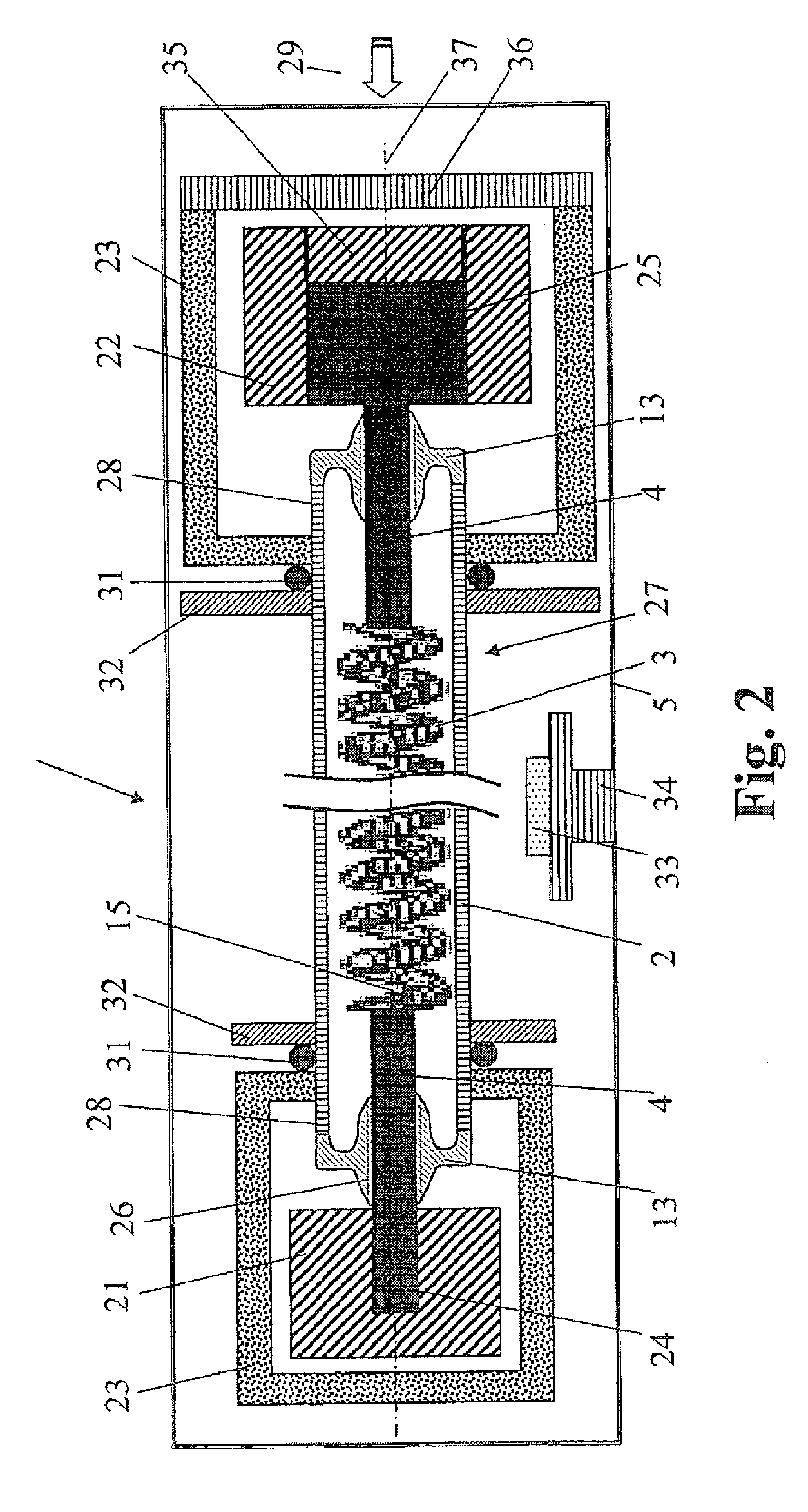
[0081]FIG. 2 shows schematically a vacuum irradiation device for a rough vacuum and a fine vacuum, having a vacuum chamber 20, in which two bus bars 21, 22 are arranged in pairs. These are each provided with a sheathing 23 made of non-conductive, heat-resistant plastic, which prevents sparkovers between the bus bars 21, 22 and the surroundings.
[0082]In the sheathing 23 openings are formed, through each of which exactly one emitter tube 2 passes, wherein the bus bars 21, 22 lying in the interior of the sheathing 23 also have, axial to the opening, a ...
PUM
 Abstract
Description
Claims
Application Information
 - R&D
- Intellectual Property
- Life Sciences
- Materials
- Tech Scout
- Unparalleled Data Quality
- Higher Quality Content
- 60% Fewer Hallucinations
Browse by: Latest US Patents, China's latest patents, Technical Efficacy Thesaurus, Application Domain, Technology Topic, Popular Technical Reports.
© 2025 PatSnap. All rights reserved.Legal|Privacy policy|Modern Slavery Act Transparency Statement|Sitemap|About US| Contact US: help@patsnap.com


