
Optimization of separation for viscous suspensions

a technology of viscous suspension and separation method, which is applied in the field of viscous source material separation, can solve the problems that large volumes of highly specific therapeutic proteins are neither inexpensive nor readily available, and achieve the effect of maximizing yield and lowering costs

Active Publication Date: 2014-08-05
SMARTFLOW TECH
View PDF46 Cites 8 Cited by
  • Summary
  • Abstract
  • Description
  • Claims
  • Application Information

AI Technical Summary

Benefits of technology

The present invention is a method and apparatus that can dilute a viscous starting material to isolate and concentrate the desired product from the starting material in a cost-effective and efficient manner. The process can be scaled up or down and is adaptable for both laboratory and industrial applications. The method involves contacting the viscous source material with a diluent, which reduces the viscosity of the source material and creates a continuous stream of diluted source material. The diluent is stored in a separate vessel from the source material. The technical effects of this invention are minimized waste and maximized yield of desired product.

Problems solved by technology

This is extremely important in the pharmaceutical market as large volumes of highly specific therapeutic proteins are neither inexpensive nor readily available.

Method used


Image

  • Optimization of separation for viscous suspensions
  • Optimization of separation for viscous suspensions
  • Optimization of separation for viscous suspensions

Examples


experiment 1

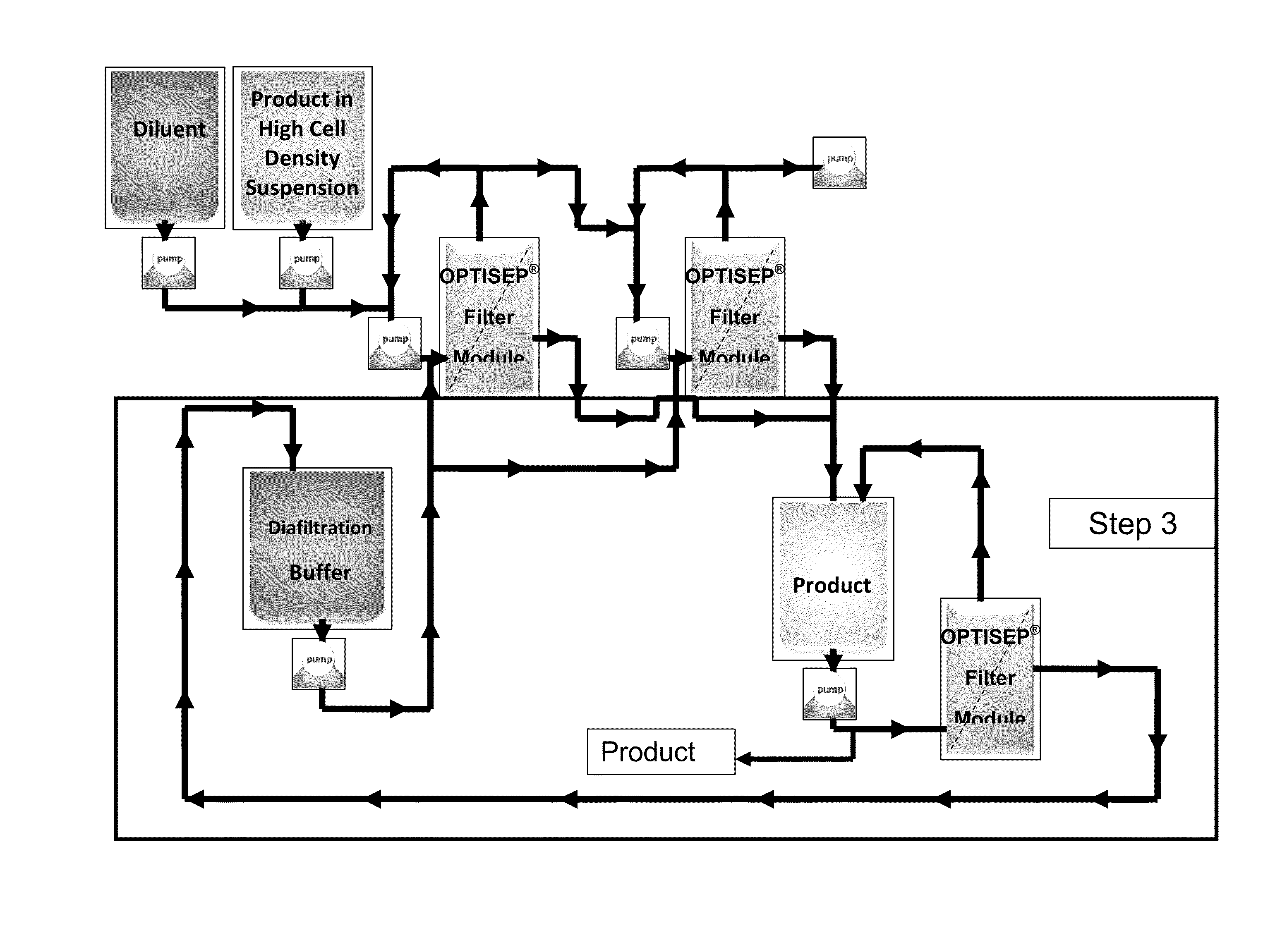
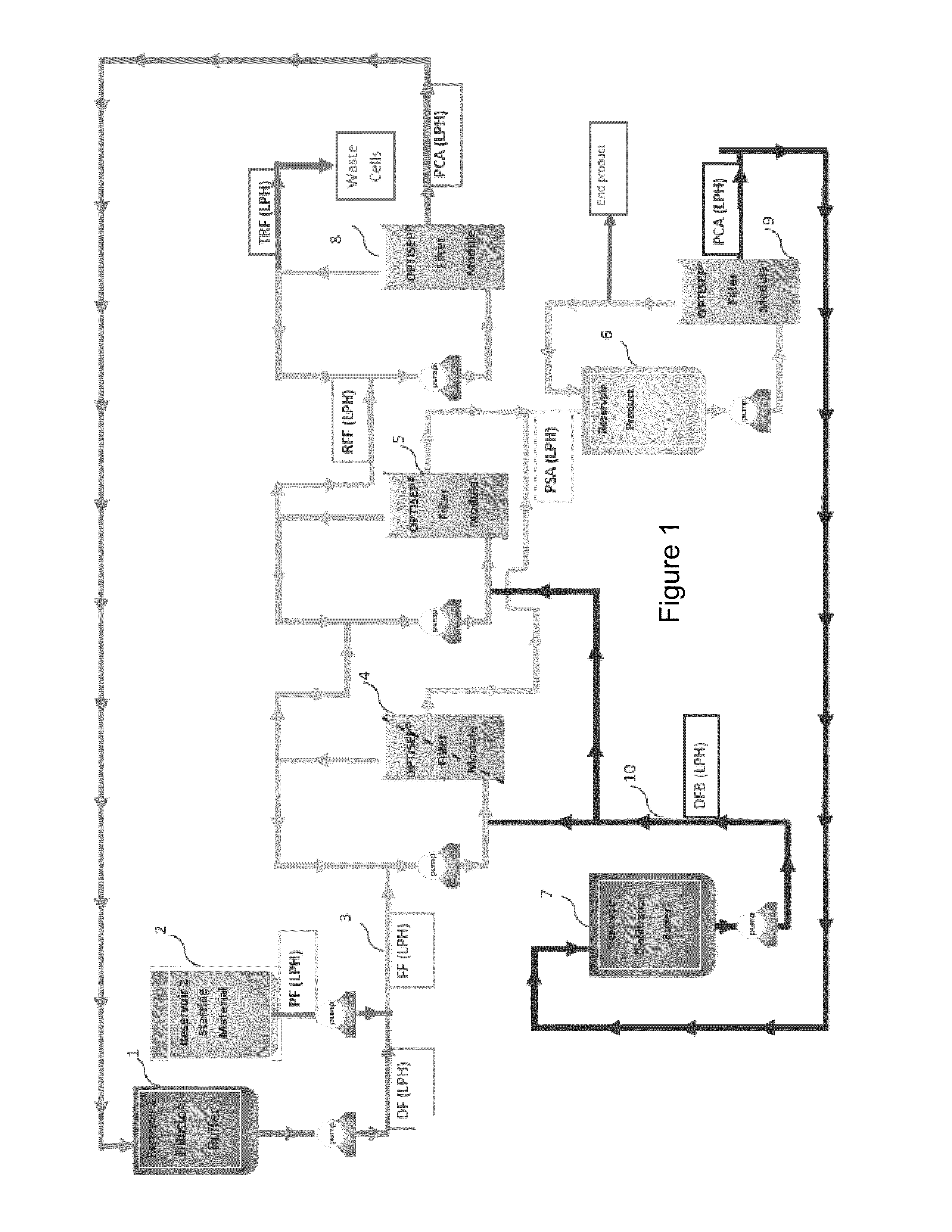
[0222]The purpose of experiment 1 is to demonstrate the passage of the product away from the diluted cell suspension. Experiment 1 is performed at various dilution rates to optimize product recovery, minimize the rate of dilution and maximize the membrane performance in liters per meter square per hour (LMH). The starting material is diluted in a batch mode using different levels of diluent to determine the appropriate dilution and the product is separated from the diluted starting material via constant volume diafiltration. The level of diafiltration is determined.

experiment 2

[0223]The purpose of experiments 2 is to concentrate the permeate of experiment 1. The permeate of experiment 1 contains the product which was separated from the cells by constant volume diafiltration of the cells. The permeate of the separation is concentrated in order to demonstrate recovery of the product and number of passes through MF for acceptable product concentration.

experiment 3

[0224]The purpose of experiments 3 is to concentrate the diafiltered retentate of experiment 1 in order to demonstrate the ability to return the cell mass to the original undiluted volume or less. In other words the purpose of experiment 3 is to show the feasibility of reducing the volume of the process waste stream as well as the ability to recover the diluent. The diluted cellular material is concentrated to the original starting volume or less and number of passes through MF for acceptable concentration.

[0225]Another embodiment for optimization comprises performing experiments 1, 2 and 3 utilizing three (3) different filtration steps (MF, UF of the MF permeate, and UF of cells); followed by a experiment 4 (FIG. 11) which is the simultaneous operation of the MF separation and the UF concentration of the MF permeate fluid.


PUM


Abstract

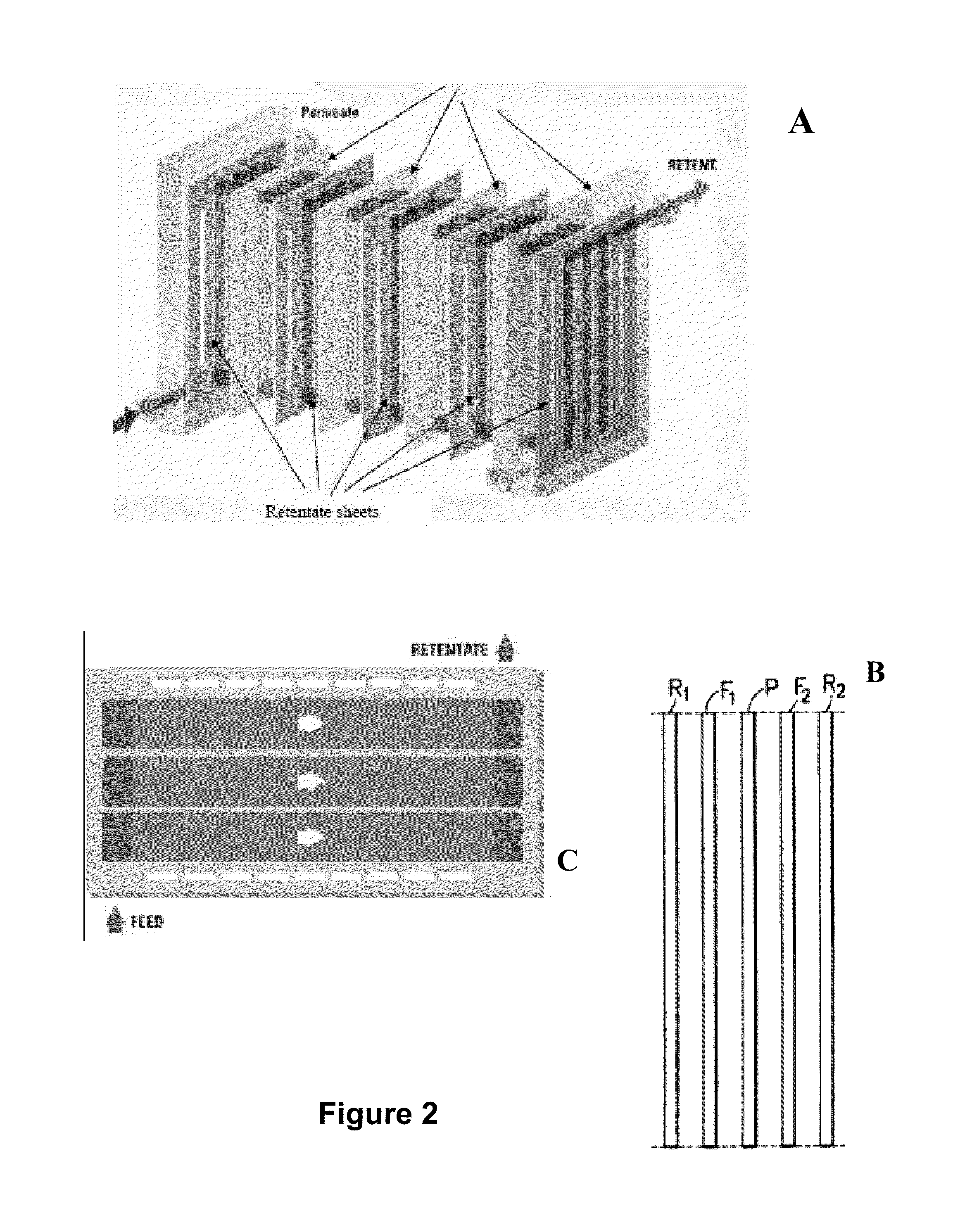
The present invention relates to methods and systems for optimization of dilution of a viscous starting material to isolate and / or concentrate the product of interest from the starting source material such that the process minimizes the volume of diluent and the total volume of the waste stream generated during the process as well as maximizing the yield of desired product. The system employs cross-flow filtration modules with sub-channels that are equidistant to the inlet and outlet of said modules and such modules are characterized by optimal channel height, optimal transmembrane pressure, etc., which are selected in order to achieve the best combination of product quality and production yield.

Description

CROSS-REFERENCE TO RELATED APPLICATIONS[0001]This application is filed under the provisions of 35 U.S.C. §371 and claims the priority of International Patent Application No. PCT / US2010 / 021626 filed on Jan. 21, 2010, which in turn claims priority to U.S. Provisional Patent Application Ser. No. 61 / 146,142 filed on Jan. 21, 2009 and U.S. Provisional Patent Application Ser. No. 61 / 148,959, filed on Jan. 31, 2009, the contents of which are incorporated herein by reference in their entirety.BACKGROUND OF THE INVENTION[0002]1. Field of Invention[0003]The present invention relates to separation of viscous source materials, and more particularly, to methods and systems for optimization of dilution of a viscous starting material to isolate and / or concentrate the product of interest from the starting source material such that the process minimizes the volume of diluent and the total volume of the waste stream generated as well as maximizing the yield of desired product.[0004]2. Discussion of R...

Claims


Application Information

Patent Timeline
Patent Type & Authority Patents(United States)
IPC IPC(8): B01D61/16B01D61/14B01D61/20B01D61/22B01D61/58B01D63/08C12M1/12C12M3/06
CPCB01D61/58B01D61/147B01D61/145B01D63/082B01D2315/10B01D2317/025B01D2317/022B01D2315/16B01D61/142C07H1/08B01D29/56B01D61/146B01D61/149B01D63/0822
Inventor KOPF, HENRY B.KACMAR, JAMES A.
Owner SMARTFLOW TECH
Learn More