Magnetoresistive element, magnetic random access memory and method of manufacturing the same

a technology of magnetic random access memory and magnetoresistive elements, which is applied in the manufacture of inductance/transformer/magnets, galvano-magnetic devices, magnetic bodies, etc., can solve the problems of difficult to stop etching at the upper surface of the barrier layer of all of the magnetoresistive elements, and the manufacturing yield may be reduced, so as to achieve high reliability and yield

Active Publication Date: 2014-08-05
NEC CORP +1
View PDF22 Cites 0 Cited by
  • Summary
  • Abstract
  • Description
  • Claims
  • Application Information

AI Technical Summary

Benefits of technology

[0016]According to the present invention, a magnetoresistive element and an MRAM which have high reliability and yield can be provided.

Problems solved by technology

For this reason, when a plurality of magnetoresistive elements are manufactured, for example, for MRAM, it may not easy to stop etching at an upper surface of the barrier layer in all of the magnetoresistive elements.
As a result, manufacturing yield may lower.

Method used


Image

  • Magnetoresistive element, magnetic random access memory and method of manufacturing the same
  • Magnetoresistive element, magnetic random access memory and method of manufacturing the same
  • Magnetoresistive element, magnetic random access memory and method of manufacturing the same

Examples


first embodiment

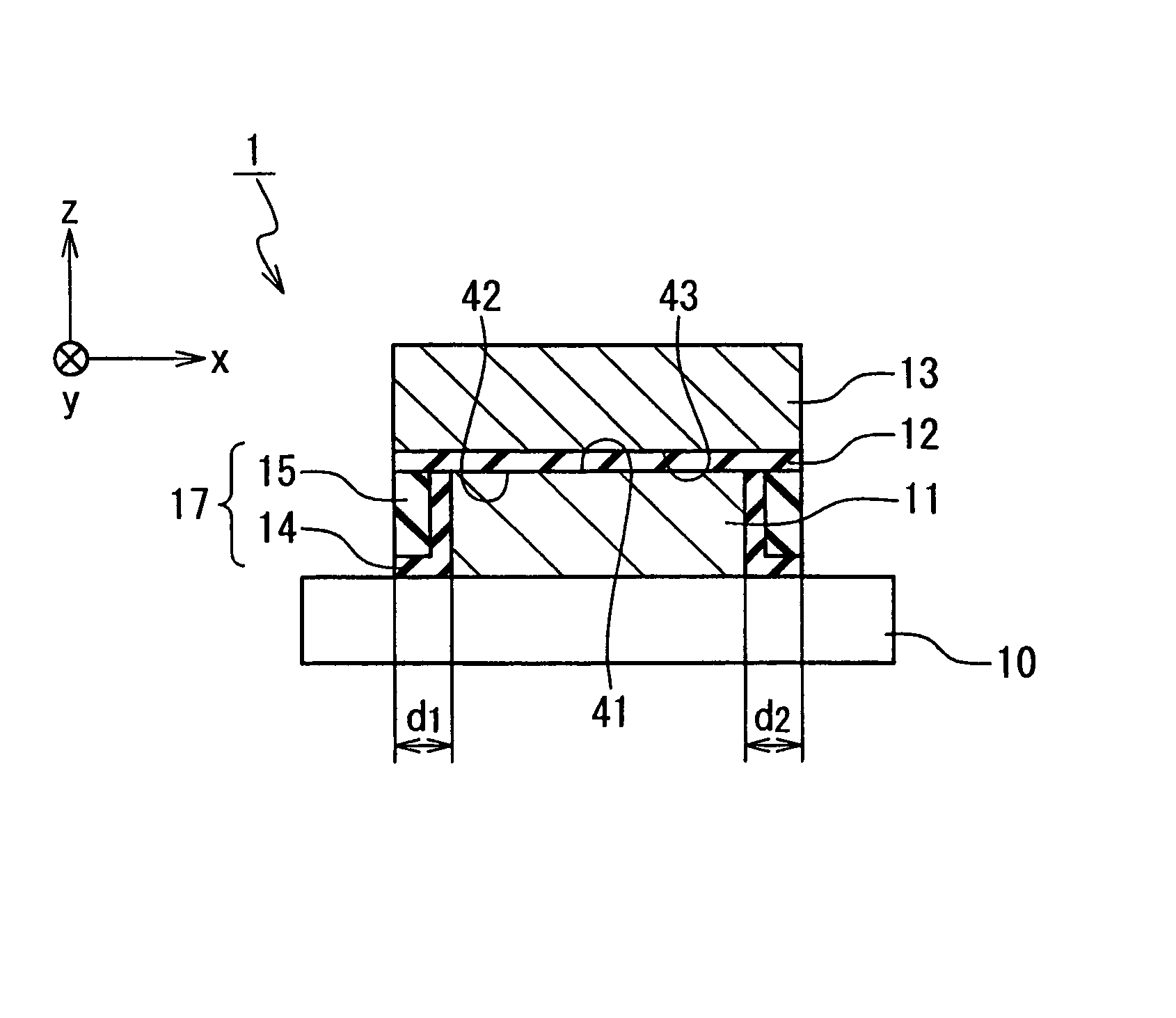
[0039]A configuration of a magnetoresistive element according to a first embodiment of the present invention will be described. FIG. 5A is a sectional view showing the configuration of the magnetoresistive element according to the first embodiment of the present invention. FIG. 5B is a top view showing the configuration of the magnetoresistive element according to the first embodiment of the present invention. The magnetoresistive element 1 includes a lower magnetic layer 11, a barrier layer 12 and an upper magnetic layer 13. Here, the case where xy planar shape of each layer is rectangular is described as an example. However, the present invention is not limited to this example and can be similarly applied to other shapes such as circle and ellipse.

[0040]The lower magnetic layer 11 is embedded in an interlayer insulating layer 17 on a substrate 10. Here, an example of the interlayer insulating layer 17 is a laminated layer of a nitride film 14 such as a SiN film and an oxide film 1...

second embodiment

[0058]A configuration of a magnetoresistive element according to a second embodiment of the present invention will be described. FIG. 7A is a sectional view showing the configuration of the magnetoresistive element according to the second embodiment of the present invention. FIG. 7B is a top view showing the configuration of the magnetoresistive element according to the second embodiment of the present invention. This magnetoresistive element 1a is different from the magnetoresistive element 1 in the first embodiment in that the upper magnetic layer 13 is a domain wall motion type magnetization recording layer. In FIG. 7A, a white arrow represents a magnetization direction in each layer (the same is also applied below).

[0059]The upper magnetic layer 13 is a ferromagnetic layer having a perpendicular magnetic anisotropy and includes a first magnetization pinned region 13a, a second magnetization pinned region 13b and a magnetization switching region 13c. A magnetization direction of ...


PUM


Abstract

A magnetoresistive element includes: a lower magnetic layer; a barrier layer; and an upper magnetic layer. The barrier layer is provided on the lower magnetic layer. The upper magnetic layer is provided on the barrier layer. One of magnetization directions of the lower magnetic layer and the upper magnetic layer is fixed. The barrier layer has a first surface which includes a surface contacted with an upper surface of the lower magnetic layer. The upper magnetic layer has a second surface which includes a surface contacted with an upper surface of the barrier layer. Each of the first surface and the second surface is larger than the upper surface of the lower magnetic layer in area.

Description

INCORPORATION BY REFERENCE[0001]This application is based upon and claims the benefit of priority from Japanese patent application No. 2009-049757 filed on Mar. 3, 2009, the disclosure of which is incorporated herein in its entirety by reference.BACKGROUND OF THE INVENTION[0002]1. Field of the Invention[0003]The present invention relates to a magnetoresistive element, a magnetic random access memory and a method of manufacturing them.[0004]2. Description of Related Art[0005]A magnetic random access memory (MRAM) has been expected as a nonvolatile memory capable of performing rewriting an infinite number of times with a high speed and actively developed. The MRAM uses a magnetoresistive element as a memory cell. An example of the magnetoresistive element is a TMR (Tunneling Magneto Resistive) element having magnetic tunneling junction (MTJ). The MTJ is composed of a free layer whose magnetization can be switched, a pinned layer whose magnetization is pinned, and a barrier layer provi...

Claims


Application Information

Patent Timeline
Patent Type & Authority Patents(United States)
IPC IPC(8): H01L43/00H01L29/82
CPCB82Y40/00B82Y25/00H01F10/3268H01L27/228H01L43/12H01L43/08H01F10/3254H01F10/3286H01F41/308H10B61/22H10N50/10H10N50/01
Inventor OZAKI, YASUAKIHONJYOU, HIROAKI
Owner NEC CORP
Why Eureka
Try Eureka