
Imaging during radiotherapy

a radiotherapy and patient technology, applied in the field of imaging during radiotherapy, can solve the problems of delay in treatment and inability to collect patients simultaneously, and achieve the effect of reducing the material cost of the system

Active Publication Date: 2014-08-05
ELEKTA AB
View PDF12 Cites 0 Cited by
  • Summary
  • Abstract
  • Description
  • Claims
  • Application Information

AI Technical Summary

Benefits of technology

Enables real-time, diagnostic-quality imaging during radiotherapy without delaying treatment, reducing material costs by using a single detection system for both beams and maintaining image quality through separate settings for each type of radiation.

Problems solved by technology

However, the switchover period between the two systems is significant, and the waiting time this would impose would therefore result in delay during treatment.
The markedly different dose rate between the two types of beams means that it is not possible to collect them simultaneously.

Method used


Image

  • Imaging during radiotherapy
  • Imaging during radiotherapy
  • Imaging during radiotherapy

Examples


Embodiment Construction

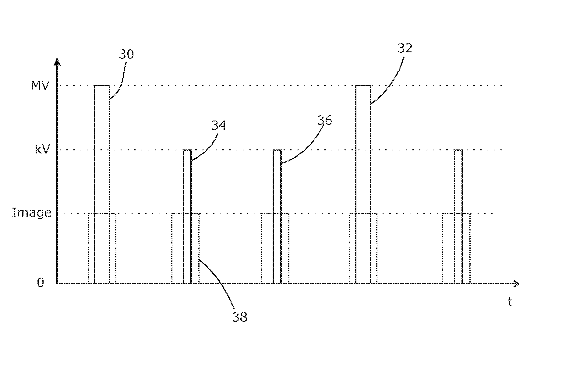
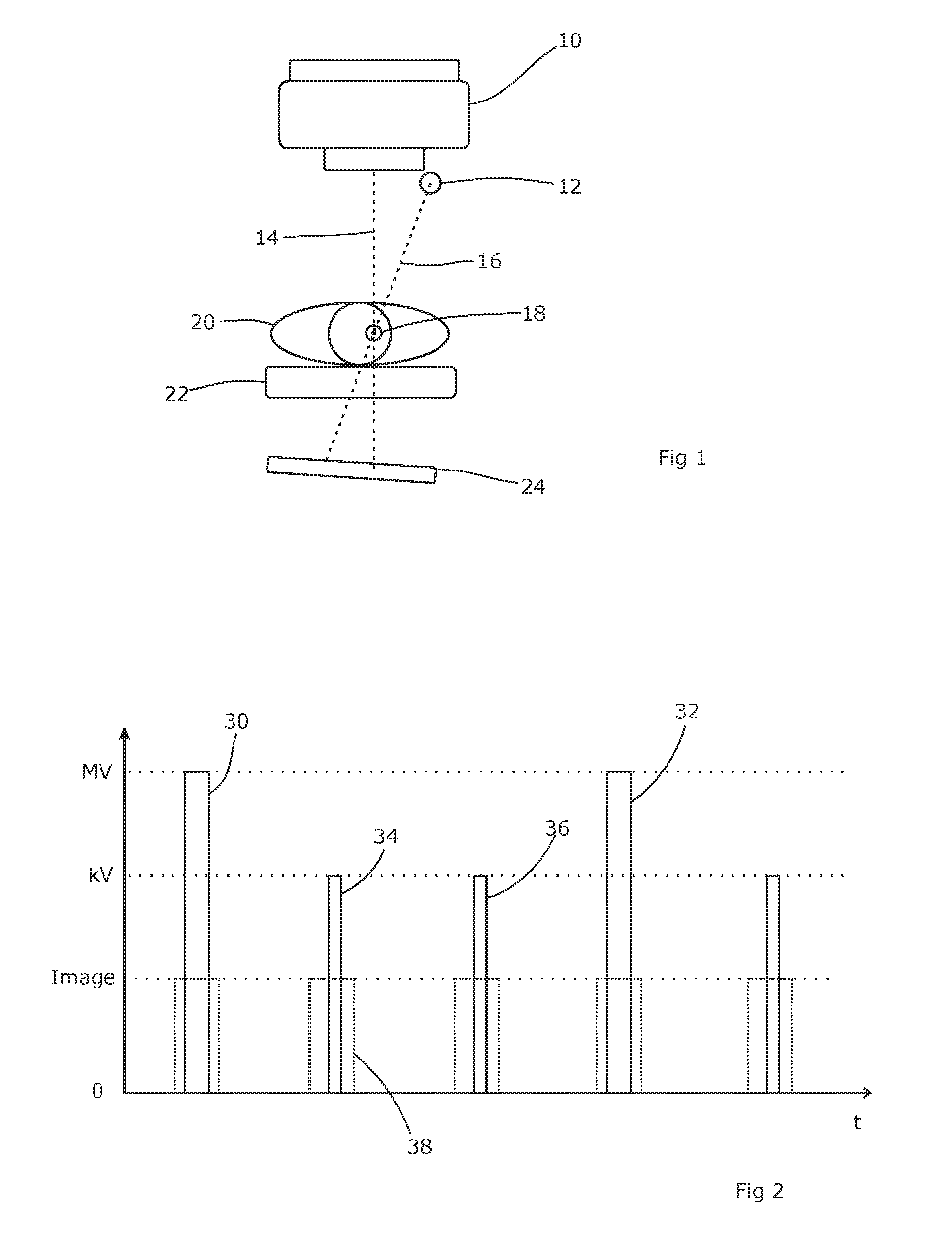
[0017]An MV beam for use in radiation therapy is typically delivered in pulses lasting 3-5 us, with a pulse repetition frequency (“PRF”) between 100-500 Hz. Accordingly, there is plenty of time (between 2 and 10 ms) to send a kV pulse of imaging radiation in between the MV pulses. By using a fast detector with a very short afterburn time (i.e. the time required for the effects of the MV pulse to dissipate), one can send one or more kV pulses between each MV pulse. This will allow the kV and MV pulses to be read and processed with the same detector, and still kept them separate from each other throughout the image processing.

[0018]A suitable detector meeting these requirements is a GEM-type detector (“Gas Electron Multiplier”). Such detectors are disclosed in WO99 / 21211, the content of which is hereby incorporated by reference and to which the skilled reader is directed for a complete understanding of the present invention. GEM detectors comprise a pair of plates separated by a suita...


PUM


Abstract

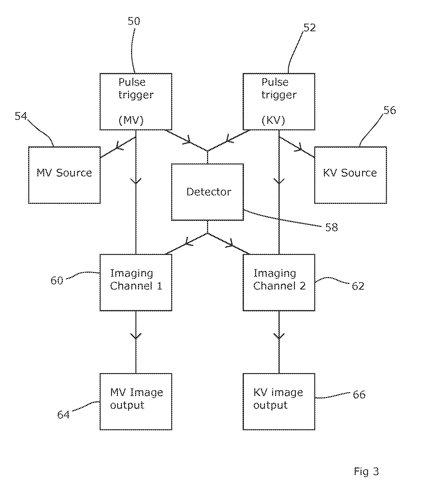
We provide a radiotherapy apparatus including a source of therapeutic radiation, a source of imaging radiation having an energy level less than that of the therapeutic radiation, a detector for radiation lying within the field of both the therapeutic radiation and the imaging radiation and able to image both, a first imaging circuit supplied with the output of the detector, a second imaging circuit also supplied with the output of the detector, a first pulse trigger circuit adapted to trigger the source of therapeutic radiation to produce a pulse of therapeutic radiation and to trigger the first imaging circuit to capture an output of the detector; and a second pulse trigger circuit adapted to trigger the source of imaging radiation to produce a pulse of imaging radiation and to trigger the second imaging circuit to capture an output of the detector.

Description

FIELD OF THE INVENTION[0001]The present invention relates to methods of (and apparatus for) imaging a patient during a radiotherapy treatment.BACKGROUND ART[0002]Radiotherapy is often carried out by directing a high-energy beam of x-rays, typically at an energy level of several MeV, towards a tumour within a patient. This beam damages tissue that it passes through, tumour tissue more so than healthy tissue, so is collimated to reduce the amount of healthy tissue that is exposed to the beam. It is also directed towards the patient from a number of different directions, each passing through the tumour or other target point, so that any particular section of healthy tissue only receives a fraction of the total dose delivered during that treatment session (or “fraction”). This can be done by mounting the beam source on a gantry that is rotatable around the patient, thereby allowing it to be delivered from any chosen angle. Usually, the patient will be supported so that the tumour lies a...

Claims


Application Information

Patent Timeline
Patent Type & Authority Patents(United States)
IPC IPC(8): A61N5/10A61B6/03
CPCA61N5/1049A61N2005/1061
Inventor CLAESSON, .ANG.KE
Owner ELEKTA AB
Learn More