
Device and method for driving liquid discharge head, liquid discharge apparatus, and ink-jet apparatus

a liquid discharge head and liquid discharge technology, which is applied in the direction of printing, inking apparatus, other printing apparatus, etc., can solve the problems of lowering the productivity of printers, difficulty in matching the droplet speed between different ink drops, and inability to form high-quality images, etc., to achieve improved droplet landing position accuracy, high picture quality, and high productivity

Active Publication Date: 2014-08-12
FUJIFILM CORP
View PDF4 Cites 3 Cited by
  • Summary
  • Abstract
  • Description
  • Claims
  • Application Information

AI Technical Summary

Benefits of technology

[0009]On the other hand, in the technique described in JP-2006-224471A, since the driving waveform (medium dot waveform, particularly see reference numeral P3 in FIG. 10C of JP-2006-224471A) for forming the medium dot is completely different from the driving waveform (see reference numeral P2 in FIG. 10B of JP-2006-224471A) for forming the small dot, the overall waveform becomes lengthened. Because of this, the recording period of one dot is lengthened, and the ink is unable to be discharged at a high frequency, thus lowering the productivity of a printer.
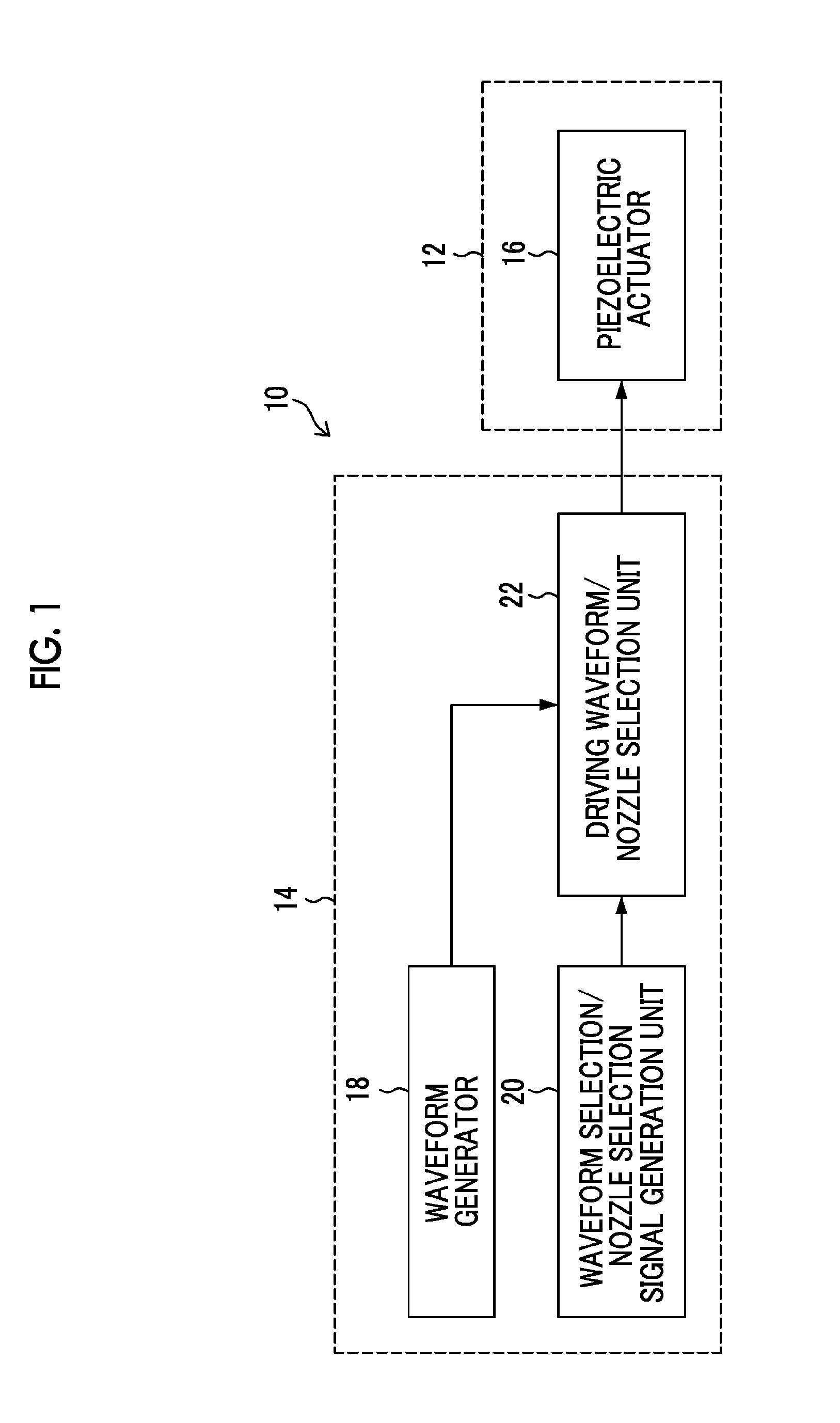
[0010]The present invention has been made in view of such situations, and an object of the invention is to provide a device for driving a liquid discharge head, a liquid discharge apparatus, and an ink-jet apparatus, which adopt a multi-drop method, secure high-precision in landing position through suppressing the difference in speed between discharge droplets due to different droplet quantities, and realize discharge at a high frequency.
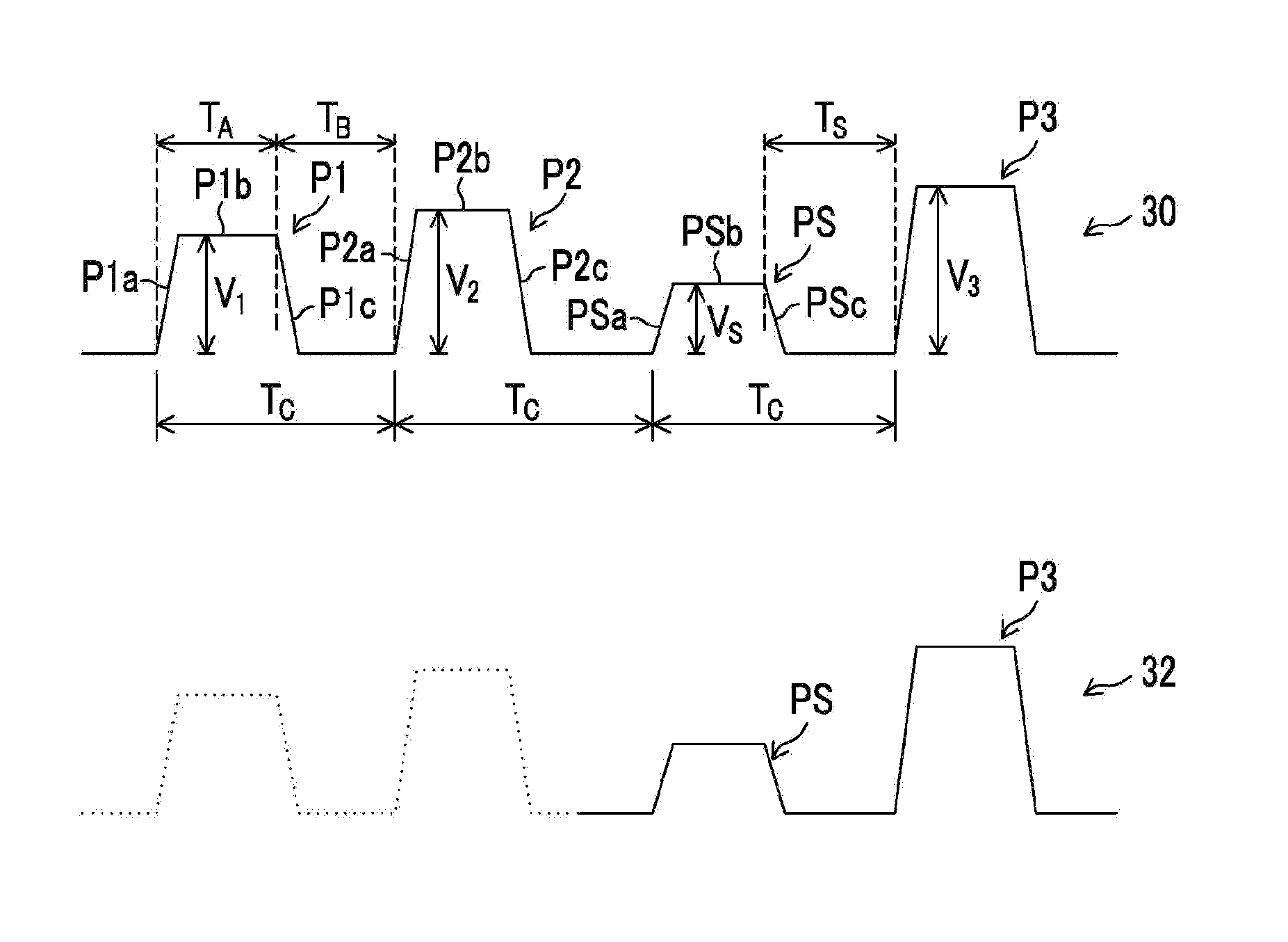
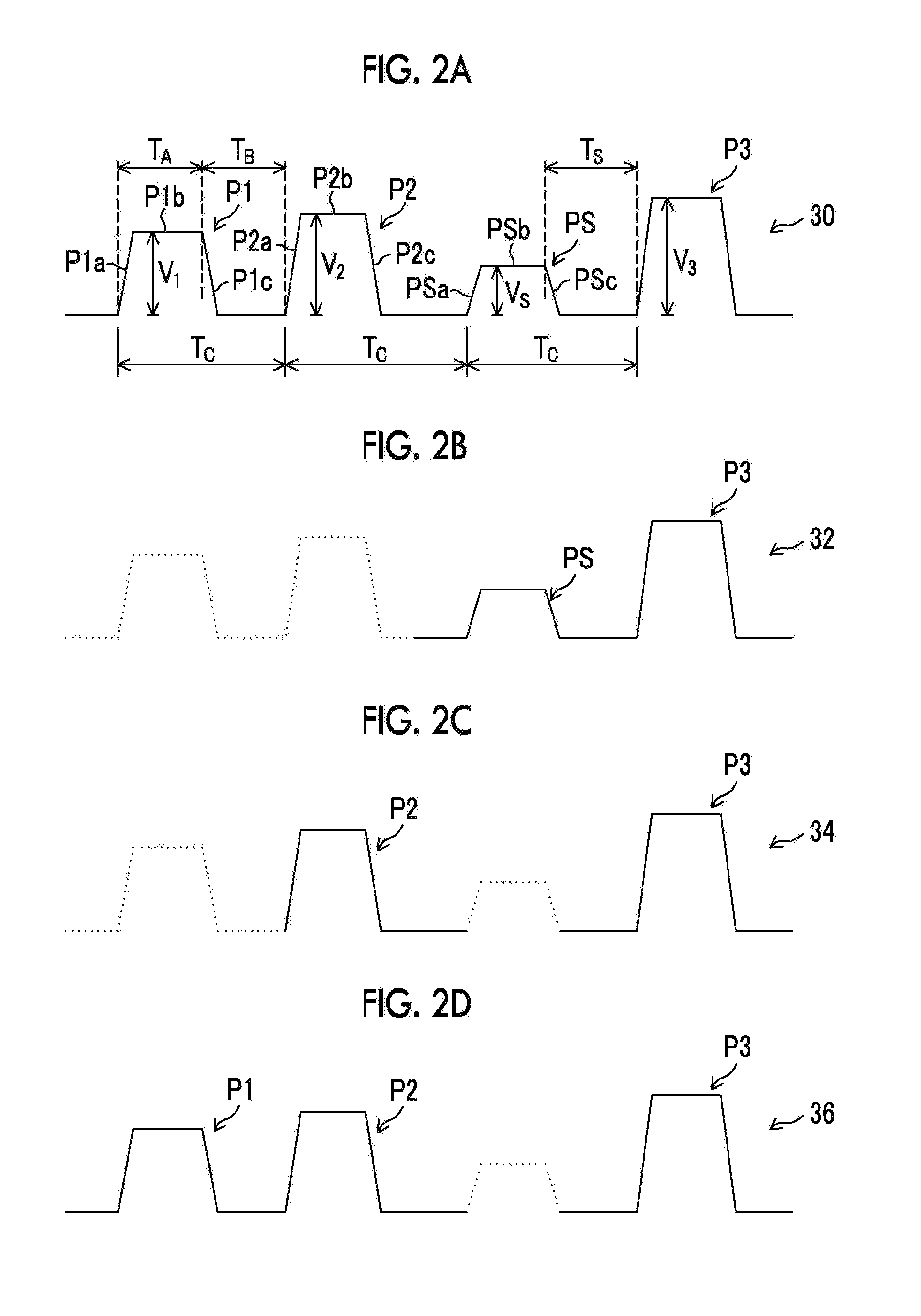
[0013]When the last jet pulse is solely used for discharging, the non-jet pulse is applied to the discharge energy generation element in combination with the last jet pulse (first driving signal), and serves to adjust the speed of the droplet being discharged.
[0014]In the case of performing the discharge (jet) operation twice or more through combining the last jet pulse with another jet pulse, a second driving signal, from which the non-jet pulse has been removed, is applied to the discharge energy generation element. Through this, it becomes possible to match the speed of a droplet (first droplet quantity) that is discharged through application of the first driving signal and the speed of droplet due to another droplet quantity (second droplet quantity) that is discharged through application of the second driving signal. Further, since the basic driving waveform includes all the waveforms of the driving signals required to discharge various droplet quantities and the droplet quantities can be changed by the number of jet pulses extracted from the basic driving waveform, the length of the overall waveform can be shortened.
[0017]According to the present invention, since the multi-drop method is adopted and the deviation in speed between the discharge droplets by the different droplet quantities can be suppressed, the precision of the landing positions of the droplets can be improved. Further, the discharge at a high frequency can be realized. According to the present invention, a printer with both the high picture quality and the high productivity can be realized.

Problems solved by technology

However, if the method that is described in JP1999-348320A (JP-H 11-348320A) is used, it is necessary to use a common jet pulse between ink drops having different dot sizes, and thus it is difficult to match the droplet speed between different ink drops.
Because of this, the landing position of the droplet slips off due to different ink drop quantities, and as a result, a high-quality image is unable to be formed.
Because of this, the recording period of one dot is lengthened, and the ink is unable to be discharged at a high frequency, thus lowering the productivity of a printer.

Method used


Image

  • Device and method for driving liquid discharge head, liquid discharge apparatus, and ink-jet apparatus
  • Device and method for driving liquid discharge head, liquid discharge apparatus, and ink-jet apparatus
  • Device and method for driving liquid discharge head, liquid discharge apparatus, and ink-jet apparatus

Examples


modified example 1

[0080]It is also possible to provide a configuration that adds a reverberation restraint pulse (which may be called a meniscus correction unit or a reverberation restraint unit) for restraining the reverberation of the meniscus after discharging just after the last jet pulse P3 in the basic driving waveform 30 illustrated in FIG. 2A. In this case, the reverberation restraint pulse can be added to the driving waveform for discharging each of the droplets of the small droplet, the medium droplet, and the large droplet.

[0081]By combining the reverberation restraint pulse, the discharge efficiency of the last pulse can be further improved, and the meniscus vibration (reverberation) after discharging one recording period can be reduced to be able to seek the stabilization of consecutive recording.

modified example 2

[0082]Although it is exemplified that the driving waveforms illustrated in FIGS. 2A to 2D are configured to draw the meniscus into the pressure chamber direction through making the pressure chamber expand by a rising portion of the pulse to raise the voltage in the plus direction from the reference potential, it is also possible to adopt a configuration which performs a “pulling” operation for drawing the meniscus through making the pressure chamber expand by a falling portion of the pulse that lowers the voltage from the reference potential, and performs a “pushing” operation through contracting the pressure chamber by a rising portion to raise the voltage from the lowered voltage.

[0083]Regarding Kinds of Droplet Sizes

[0084]Although it has been described that three kinds of droplets, that is, the small, medium, and large droplets, are provided, the kinds of droplets can be generalized as follows. That is, it is possible to perform discharge with different droplet quantities by sele...


PUM


Abstract

A basic driving waveform which includes a plurality of jet pulses and a non-jet pulse just before the last jet pulse in one recording period is generated. A part of the pulses is removed from the basic driving waveform by maintaining at least the last jet pulse, and a driving signal that is applied to a discharge energy generation element is generated. In the case of using only the last jet pulse among the plurality of jet pulses is used for the jet, a first driving signal that includes the non-jet pulse just before the last jet pulse is generated. In the case of joining the last jet pulse and at least another jet pulse among the plurality of jet pulses to use the pulses for the jet, a second driving signal that is configured to remove the non-jet pulse is generated.

Description

BACKGROUND OF THE INVENTION[0001]1. Field of the Invention[0002]The present invention relates to a discharge control technique that performs landing with several kinds of dot sizes by changing the droplet quantity that particularly forms one dot in association with a device and a method for driving a liquid discharge head, a liquid discharge apparatus, and an ink-jet apparatus.[0003]2. Description of the Related Art[0004]In an ink-jet apparatus, a so-called multi-drop type gradation printing is known which changes the number of ink jet drops being jetted to 1, 2, 3, . . . with respect to printing data that corresponds to a record of one dot (landing point of one pixel) when recording an image by forming dots with ink drops on a recording medium such as paper or the like, and forms one-dot droplets by joining the plurality of ink drops (JP1999-348320A (JP-H 11-348320A) and JP-2006-224471A). By adopting this method, a high quality image can be formed.[0005]In the multi-drop type grada...

Claims


Application Information

Patent Timeline
Patent Type & Authority Patents(United States)
IPC IPC(8): B41J29/38
CPCB41J2/04528B41J2/04581B41J2/04588B41J2/04593B41J2/04595B41J2/04596B41J2002/14459B41J2202/20B41J2202/21
Inventor TSUKAMOTO, RYUJI
Owner FUJIFILM CORP
Learn More