Optical coherence tomography apparatus and method

a coherence tomography and optical coherence technology, applied in the field of optical coherence tomography apparatus and method, can solve the problems of reducing sensor sensitivity, difficulty in increasing vertical resolution, and wavelength band also having a limit on a long wavelength sid

Inactive Publication Date: 2014-08-12
CANON KK
View PDF9 Cites 2 Cited by
  • Summary
  • Abstract
  • Description
  • Claims
  • Application Information

AI Technical Summary

Benefits of technology

[0022]In order to solve the above problems, an optical coherence tomography apparatus acquiring a tomographic image of an object to be inspected based on an interference light obtained by causing a return light from a measuring light emitted onto the object to be inspected to interfere with a reference light corresponding to the measuring light, the apparatus comprising: a first dispersion compensation unit having a first dispersion compensation characteristic in a wavelength band of the measuring light; a second dispersion compensation unit provided onto the first dispersion compensation unit and having a second dispersion compensation characteristic in the wavelength band of the measuring light.

Problems solved by technology

Accordingly, it is difficult to increase the vertical resolution by reducing the central wavelength in the wavelength band used by the ophthalmologic OCT system.
Further, the wavelength band also has a limit on a long wavelength side because of absorption loss by vitreous body in front of the eye fundus portion and reduction in sensor sensitivity.
Unfortunately, the dispersion characteristics of an object to be measured are different for each wavelength, and thus a broader wavelength band makes it difficult to compensate dispersion by a single material, which may suppress the increase in vertical resolution.
Thus, it is difficult to perform dispersion compensation on water over the broadband by the apparatus configuration disclosed in the above document.
Unfortunately, this configuration has a problem in routine use because the dispersion compensation using water involves management difficulty and quality deterioration.

Method used


Image

  • Optical coherence tomography apparatus and method
  • Optical coherence tomography apparatus and method
  • Optical coherence tomography apparatus and method

Examples


first embodiment

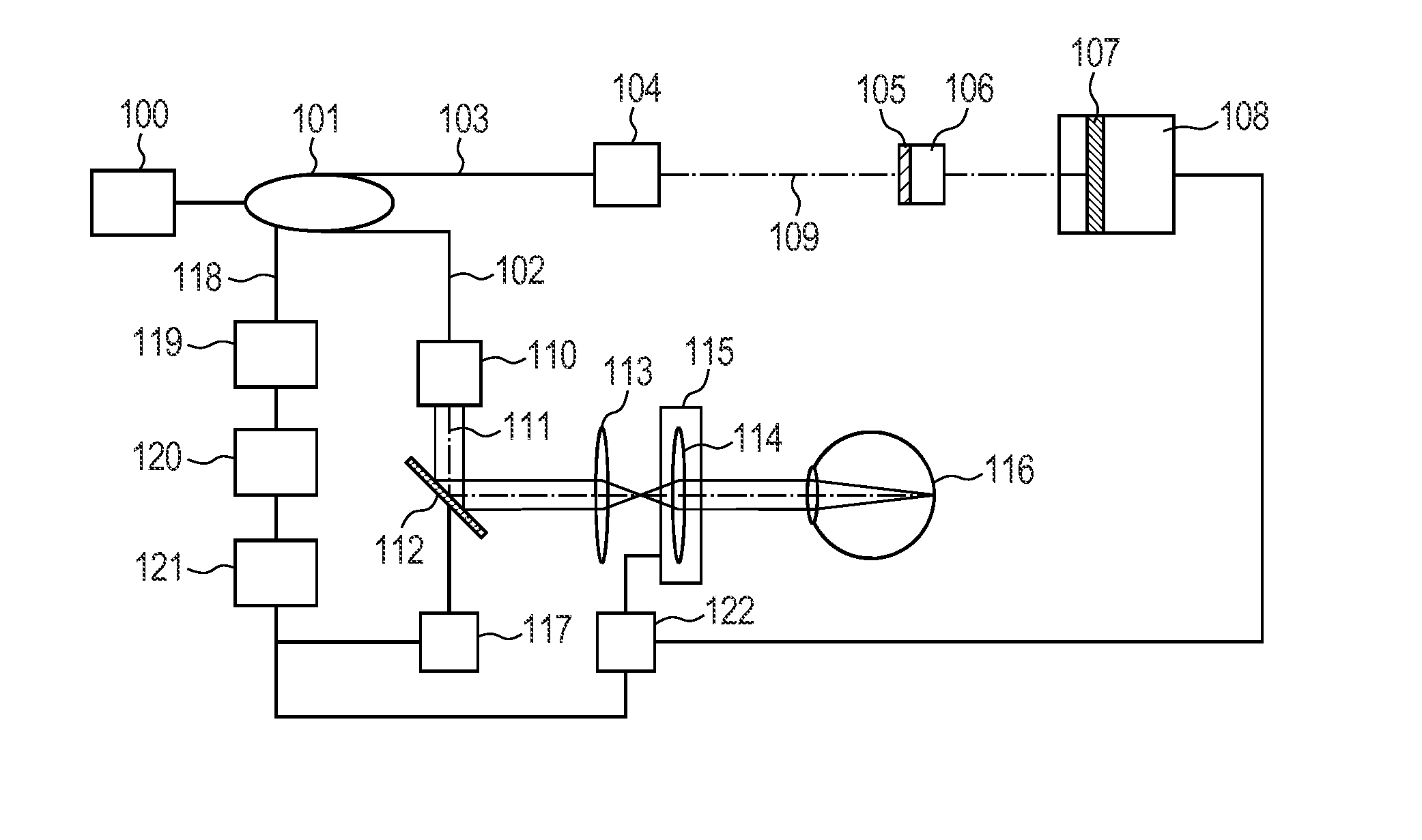
[0035]With reference to FIG. 1, an optical coherence tomography apparatus according to the present invention will be described.

[0036]FIG. 1 illustrates the optical coherence tomography apparatus as a specific example for carrying out the present invention.

[0037]In FIG. 1, a light source 100 is an SLD (Super Luminescent Diode) in the present embodiment, but may be any low-coherence light source. The specific examples include an ASE (Amplified Spontaneous Emission) light source, an ultrashort pulse light source such as a titanium sapphire laser and an SC (Super Continuum) light source, and an SS (Swept Source) light source. The wavelength band is near 850 nm, but it is desirable that the wavelength band be selected according to the purpose because if a deeper portion of the object to be inspected needs to be measured at the expense of the vertical resolution, a light source having a longer wavelength band is used.

[0038]A fiber coupler 101 splits broadband light emitted from the light ...

second embodiment

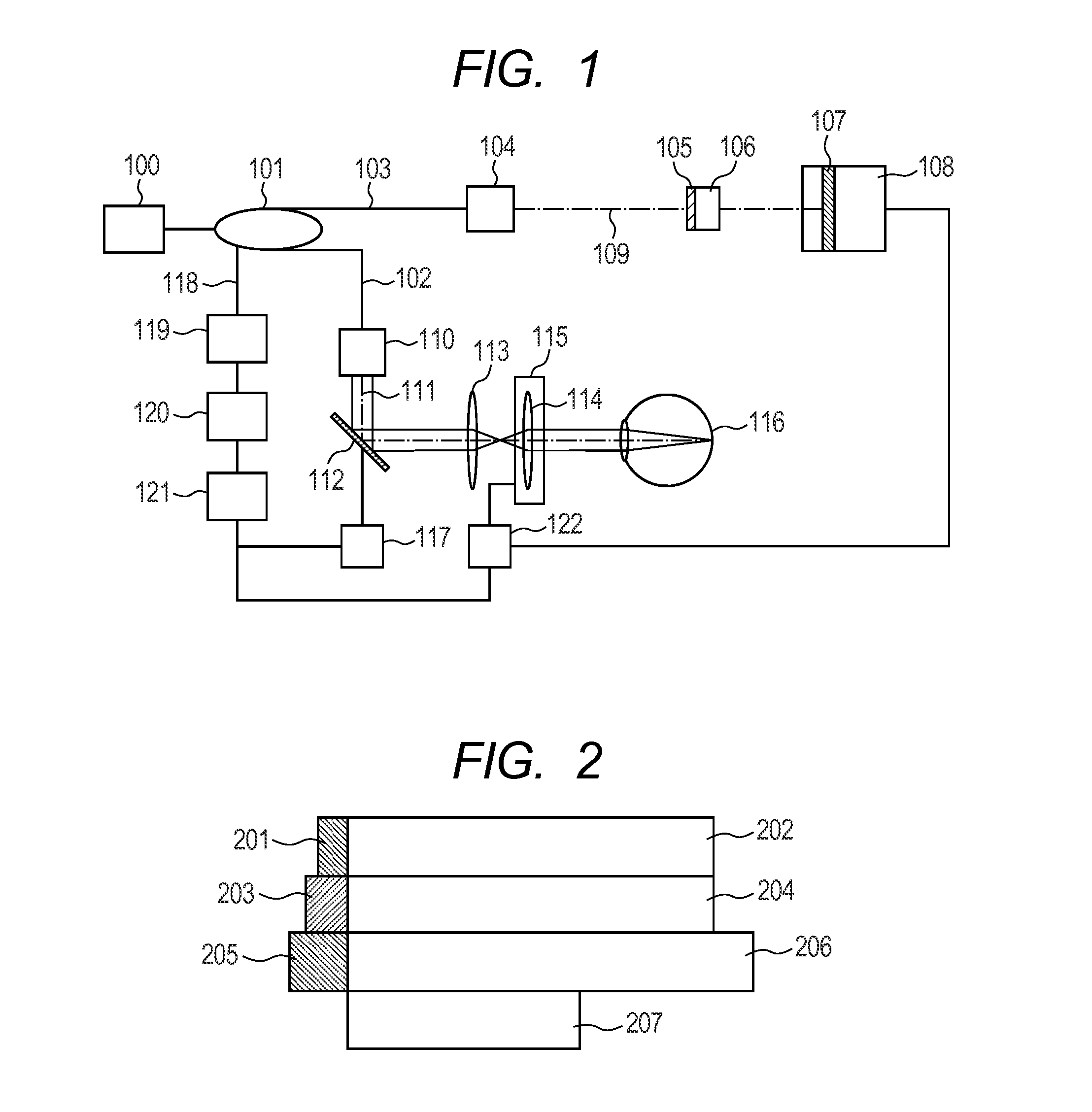
[0063]In the present embodiment, a plurality of composite dispersion compensation members including materials 1 and 2 satisfying expression (4) is arranged each having a different thickness as illustrated in FIG. 2.

[0064]The present embodiment can provide the dispersion compensation members each suitably compensating for nearsightedness, normal sightedness, or farsightedness. FIG. 2 illustrates dispersion compensation members 201 and 202 for use in measuring an object to be inspected for farsightedness; dispersion compensation members 203 and 204 for normal sightedness with normal axial length; and dispersion compensation members 205 and 206 for nearsightedness. More specifically, the present embodiment uses the conditions listed in the following Table 1.

[0065]

TABLE 1ThicknessThicknessPolycarbonate(mm)BK7(mm)2011.7202232032204232052.220623.7

[0066]A dispersion compensation member 207 is provided for calibration when a schematic eye or a mirror is placed as the object to be inspected....


PUM


Abstract

Measuring light with a wide wavelength band is used to provide a tomographic image excellent in vertical resolution. An optical coherence tomography apparatus acquiring a tomographic image of an object to be inspected based on an interference light obtained by causing a return light from a measuring light emitted onto the object to be inspected to interfere with a reference light corresponding to the measuring light, includes: a first dispersion compensation unit having a first dispersion compensation characteristic in a wavelength band of the measuring light; a second dispersion compensation unit provided onto the first dispersion compensation unit and having a second dispersion compensation characteristic in the wavelength band of the measuring light.

Description

BACKGROUND OF THE INVENTION[0001]1. Field of the Invention[0002]The present invention relates to an optical coherence tomography apparatus and method, and more particularly to an optical coherence tomography apparatus and method for imaging a cross-section of the eye fundus and skin.[0003]2. Description of the Related Art[0004]Recent years have seen a practical use of an optical coherence tomography (hereinafter referred to as an OCT) apparatus using an optical coherence technique with low coherence light. The OCT apparatus is a useful apparatus in a medical field, especially in an ophthalmic field. The OCT apparatus can provide a tomographic image of an eye fundus retinal portion and is becoming essential to the diagnosis of diseases of an eye fundus portion.[0005]Here, the principle of the OCT will be described in brief. The low coherence light is divided into reference light and measuring light. The measuring light is incident on an object to be inspected and is reflected on a to...

Claims


Application Information

Patent Timeline
Patent Type & Authority Patents(United States)
IPC IPC(8): A61B3/14
CPCA61B3/102A61B5/0066A61B3/12G01N21/45
Inventor KUROSAKA, RYOJI
Owner CANON KK
Why Eureka
Try Eureka