Miniature linear motion guide unit with lubrication system

a lubrication system and motion guide technology, applied in the direction of linear bearings, shafts, bearings, etc., can solve the problems of formidable assemblage of tiny parts, unsuitable miniaturization or downsizing of the prior rolling guide unit, etc., to simplify the assembly of the lubricant applicator, easy to set and seal, and maintain accurate alignment with each other

Active Publication Date: 2014-08-12
NIPPON THOMPSON
View PDF14 Cites 1 Cited by
  • Summary
  • Abstract
  • Description
  • Claims
  • Application Information

AI Technical Summary

Benefits of technology

[0007]The present invention has for its primary object to overcome the major challenge as stated earlier, and to provide a ball-spline in which a porous compact lubricant applicator fits in an outward end surface of an end cap, the porous compact lubricant applicator having a volumetric size enough to preserve therein a desired amount of lubricant, and a retainer plate or disc is built in the end cap and held in place with a snap-fit engagement with the end cap to keep the lubricant applicator in place while squeezing the lubricant applicator, whereby the miniature parts including the lubricant applicator and retainer plate are assembled into the unitary end cap. The end cap assembled in this way is combined with a carriage into a finished slider. Thus, the present invention provides a miniature linear motion guide unit with a ball-spline and a lubrication system that helps realize maintenance-free operation for lubrication over a prolonged service life.
[0019]In the present invention, a miniature linear motion guide unit with a lubrication system is disclosed in which the carriage, when viewed on the end surface thereof, has the raceway grooves at two locations spaced diametrically opposite to each other, and the return passages lying in bilateral symmetry with respect to a line lying midway between the raceway grooves, thereby making it possible to use the same end caps on either of the opposite ends surface of the carriage to complete the slider.
[0020]With the linear motion guide unit of the present invention, even if the slider is more miniature or downsized so as to fit over the guide shaft not more than 6 mm, for example 4 mm in diameter, the lubricant applicator impregnated with adequate amount of lubricant can be installed in the end cap and sealed with the retainer plate. With the linear motion guide unit constructed as stated earlier, moreover, the lug lying around the retainer plate is first brought into the recess in the circular edge of the end cap to keep in place the retainer plate circumferentially of the end cap. Then, the retainer plate is forced deep in the recess in the end cap to get the locking nose of the retainer plate snapping into the locking recess, thereby keeping axially in place the retainer plate relative to the end cap to secure the retainer plate to the end cap. Thus, the lubricant applicator may be set and sealed easily and certainly inside the end cap to provide the ball spline virtually maintenance-free for lubrication.
[0021]As the end cap and the retainer plate are both made of synthetic resins, the locking nose, despite being very small or tiny in size, is deformable elastically so as to easily snap into the locking nose to make snap-fit engagement between the retainer plate and the end cap. Further, the presser pawls on the retainer plate squeeze elastically the lubricant applicator to fasten positively the lubricant applicator, thereby facilitating and simplifying the assembly of the lubricant applicator and the retainer plate inside the end cap in such a way as to keep accurate alignment with each other. With the linear motion guide unit of the present invention, the end cap major body has the apertures to accommodate the lubricant reservoir of the lubricant applicator. Thus, whether the lubricant applicator is surely installed in the end cap major body can be visible at a glance by only looking in at the apertures from the backside of the end cap major body and, therefore no installation of the lubricant applicator will be prevented before the completion of assembly.

Problems solved by technology

This means the prior rolling guide unit constructed as stated earlier is unsuited for the miniaturization or downsizing of the unit.
Though the prior linear motion guide unit constructed as stated in this way was befitting for maintenance-free operation for lubrication, yet it remained a major challenge to develop any miniature or micromechanical ball-spline.
In conventional production of the miniature ball-spline in which tiny or minute parts were selected, discerned from each other and then assembled together, the assemblage of the tiny parts was found to be a formidable task.
This meant there remained a major challenge about how to locate microscopic pieces or parts in place, then assemble them together, and join them together while keeping them in assembled relation into the finished end cap.

Method used


Image

  • Miniature linear motion guide unit with lubrication system
  • Miniature linear motion guide unit with lubrication system
  • Miniature linear motion guide unit with lubrication system

Examples


Embodiment Construction

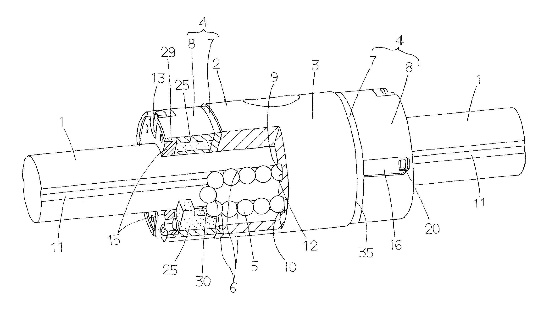
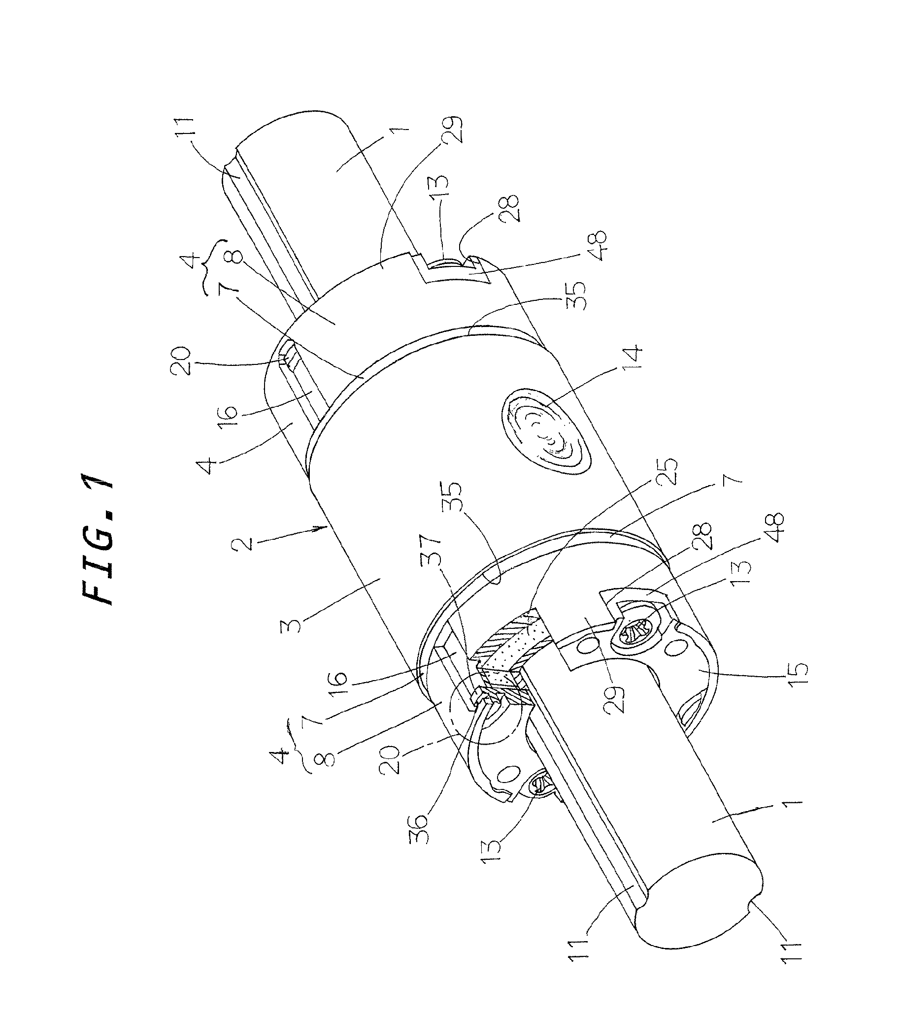
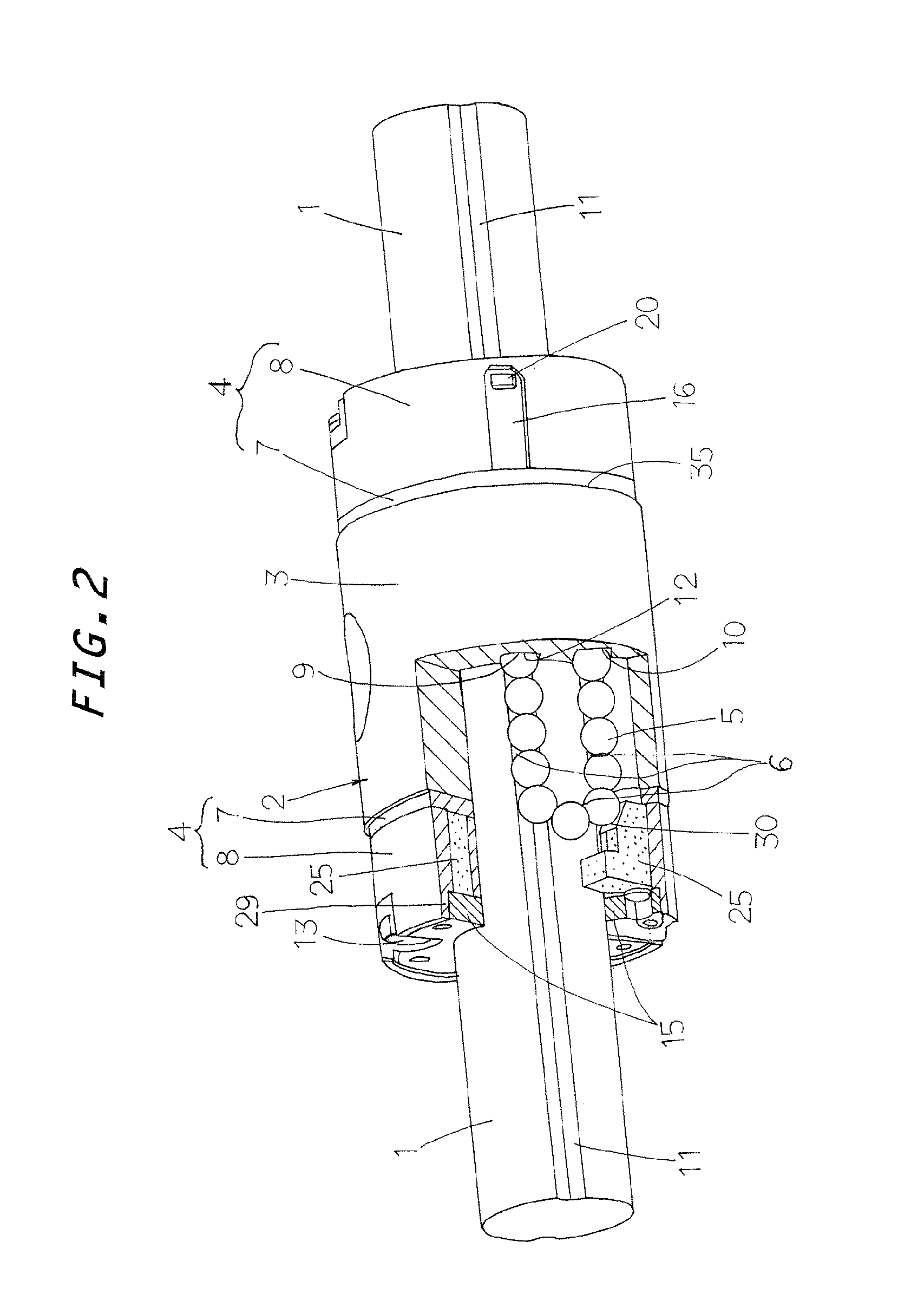
[0041]Preferred embodiments of the miniature ball-spline with a lubrication system according to the present invention will be explained hereinafter in detail with reference to the accompanying drawings. The miniature ball-spline with lubrication system of the present invention is suited for incorporating a sliding component with a rotary component which is used in combination in a diversity of machines including semiconductor fabricating equipment, assembling machines, conveying machines, and so on.

[0042]Referring first to FIGS. 1 to 3, the miniature linear motion guide unit of the present invention is generally comprised of an elongated guide shaft 1 having raceway grooves 11 lying circumferentially spaced away from each other around the guide shaft 1 and extending lengthwise of the guide shaft 1, and a slider 2 fitting over the guide shaft 1 to move in a sliding manner relatively to the guide shaft 1 through balls 5. The guide shaft 1 is made of a solid rod right circular in a tra...


PUM


Abstract

A linear motion guide unit is provided which is downsized in size, maintenance-free for lubrication, and makes it possible to assemble easily and quickly the slider with accuracy. The end cap has outward end surfaces each of which is concaved to provide a first recess to fit over a lubricant applicator of porous compact to apply the rollers while running through the turnaround passages, and a second recess to fit over a retainer plate. The retainer plate is surrounded with a peripheral edge of the end cap and held in place with a snap-fit engagement with the end cap to squeeze the lubricant applicator inside the first recess in the end cap.

Description

FIELD OF THE INVENTION[0001]The present invention relates to a miniature ball-spline in which a cylindrical slider fits over a guide shaft round in cross section having a diameter of not more than 6 mm. More particularly, it relates a miniature linear motion guide unit with lubrication system in which the slider fits over the guide shaft to move lengthwise relative to the guide shaft while transmitting mutual torque between them.BACKGROUND OF THE INVENTION[0002]Modern linear motion guide units are finding increased applications in diverse fields including various assembling machines, semiconductor manufacturing equipment, and so on. Corresponding to the downsizing requirement in the applied fields, the advanced sliding devices are more needed to meet miniaturization or downsizing in construction and maintenance-free working for lubrication. Especially, the micromechanical ball-splines frequently used as linear motion guide units in semiconductor manufacturing equipment, and so on, a...

Claims


Application Information

Patent Timeline
Patent Type & Authority Patents(United States)
IPC IPC(8): F16C33/10F16C29/06
CPCF16C33/6648F16C29/0609F16C29/0695F16C2226/74
Inventor YOSHIDA, YOSHIHIRO
Owner NIPPON THOMPSON
Why Eureka
Try Eureka