Cleaner head

a cleaning head and cleaning technology, applied in the direction of carpet cleaners, suction nozzles, brushes, etc., can solve the problems of affecting the cleaning performance of the cleaner head on such floor surfaces, and achieve the effect of inhibiting scratching or marking of the floor surfa

Active Publication Date: 2014-08-19
DYSON TECH LTD
View PDF69 Cites 31 Cited by
  • Summary
  • Abstract
  • Description
  • Claims
  • Application Information

AI Technical Summary

Benefits of technology

[0008]The agitating apparatus thus comprises two surface agitating means. The relatively short, first agitating means may be configured to agitate dirt and dust from a carpeted floor surface, whereas the relatively long, second agitating means may be configured to sweep dirt and dust from a hard floor surface. Forming this second agitating means from material having a lower surface resistivity than that from which the first agitating means is formed can enable static electricity residing on a floor surface to be cleaned to be discharged upon contact between the second agitating means and the floor surface. This enables fine dust and powder which would otherwise be attracted to the floor surface to be dislodged from the floor surface by the second agitating means.
[0016]At least two rows of the second agitating means may be in electrical contact. In a preferred embodiment, adjacent rows of the second agitating means are in electrical contact. For example, at least one agitating member of one row may also form at least one agitating member of another row. Such agitating members may pass through one or more apertures formed in the rotatable body of the agitating apparatus, or may be otherwise connected to the body so that two rows each comprise a respective end of an agitating member. In a preferred embodiment, a row of bristles or filaments is sandwiched between the rotatable body and a connecting member connected to the body so that the ends of the bristles or filaments protrude from the body to define respective rows of the second agitating means. A strip of material may be similarly connected to the rotatable body so that portions of the strip form respective rows of the second agitating means. This can simplify manufacture of the agitating apparatus, and reduce costs.

Problems solved by technology

This can impair the cleaning performance on the cleaner head on such floor surfaces, as the sweeping action of the nylon bristles is insufficient to overcome the force attracting the fine dust to the floor surface.

Method used


Image

  • Cleaner head
  • Cleaner head
  • Cleaner head

Examples


Embodiment Construction

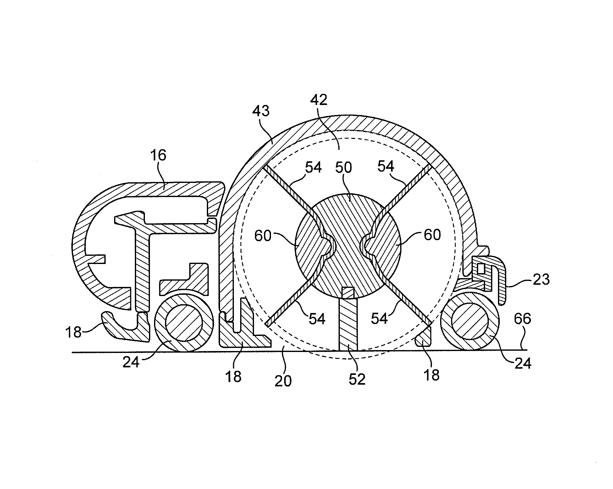
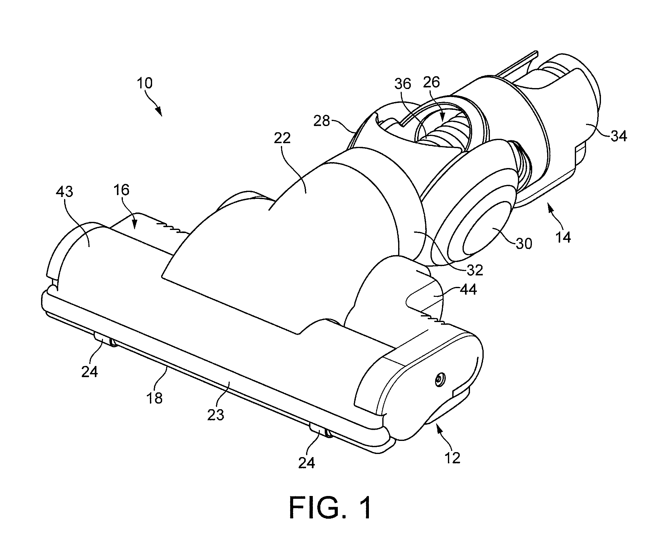
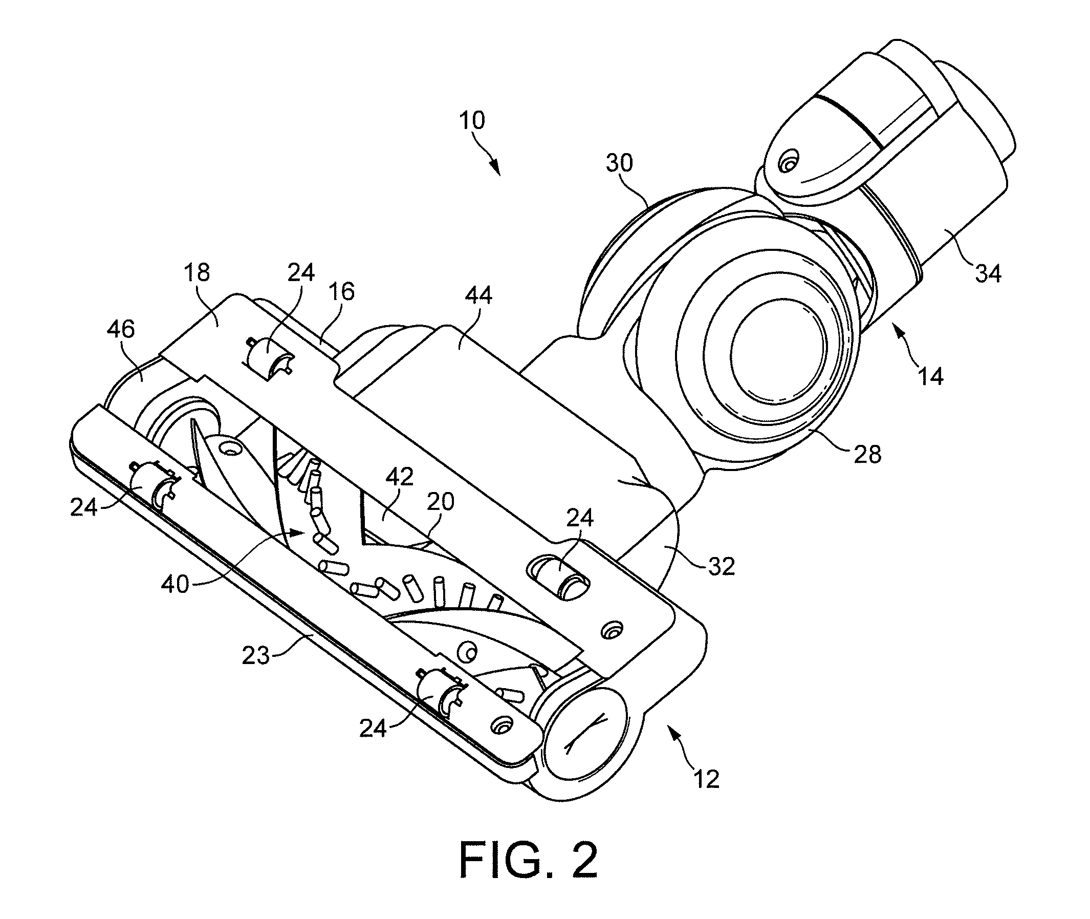
[0035]With reference first to FIGS. 1 to 3, a floor tool 10 comprises a cleaner head 12 rotatably attached to a coupling 14. The free end of the coupling 14 is attachable to a wand, hose or other such duct of a cleaning appliance (not shown). The cleaner head 12 comprises a housing 16 and a lower plate, or sole plate 18, comprising a suction opening 20 through which a dirt-bearing fluid flow enters the cleaner head 12. The housing 16 defines a suction passage extending from the suction opening 20 to an outlet duct 22 located at the rear of the housing 16. The housing 16 preferably comprises a front bumper 23. The sole plate 18 comprises a plurality of support members 24 in the form of rolling elements mounted within recessed portions of the sole plate 18 for supporting the cleaner head 12 on a floor surface. With reference to FIGS. 7 and 8, the support members 24 are preferably arranged to support the sole plate 18 above the floor surface when the cleaner head 12 is located on a har...


PUM


Abstract

A cleaner head for a surface treating appliance includes a housing and a rotatable brush bar located within the housing. The brush bar includes a first plurality of bristles and a second plurality of bristles which protrude radially outwardly beyond the first plurality of bristles. The second plurality of bristles has a surface resistivity in the range from 1×10⁻⁵ to 1×10¹² Ω / sq so that static electricity residing on a floor surface to be cleaned is discharged upon contact with the conductive bristles.

Description

REFERENCE TO RELATED APPLICATIONS[0001]This application claims the priority of United Kingdom Application No. 0909896.3, filed Jun. 9, 2009, the entire contents of which are incorporated herein by reference.FIELD OF THE INVENTION[0002]The present invention relates to agitating apparatus for a surface treating appliance, and to a cleaner head for a surface treating appliance. In its preferred embodiment, the present invention relates to a cleaner head for a vacuum cleaning appliance.BACKGROUND OF THE INVENTION[0003]A vacuum cleaner typically comprises a main body containing dirt and dust separating apparatus, a cleaner head connected to the main body and having a suction opening, and a motor-driven fan unit for drawing dirt-bearing air through the suction opening. The dirt-bearing air is conveyed to the separating apparatus so that dirt and dust can be separated from the air before the air is expelled to the atmosphere.[0004]The suction opening is directed downwardly to face the floo...

Claims


Application Information

Patent Timeline
Patent Type & Authority Patents(United States)
IPC IPC(8): A47L5/10A46B13/00A46B13/02A47L5/26A47L9/04
CPCA47L9/0477A46B13/006A46B13/02A46B2200/3033A47L9/02A47L9/04
Inventor FOLLOWS, THOMAS JAMES DUNNINGCOURTNEY, STEPHEN BENJAMIN
Owner DYSON TECH LTD
Why Eureka
Try Eureka