Grain drying system

a grain drying and grain technology, applied in drying machines, lighting and heating apparatus, furnaces, etc., can solve the problems of high fuel consumption, small or inexistent moisture movement from wet grain to moist air, and high drying rate, so as to facilitate the sensor's determination of relative humidity and accurate determination of grain condition

Active Publication Date: 2014-08-19
AGI SURETRACK LLC
View PDF20 Cites 24 Cited by
  • Summary
  • Abstract
  • Description
  • Claims
  • Application Information

AI Technical Summary

Benefits of technology

[0010]The internal sensor assemblies are preferably secured to flexible cables hung or suspended within the grain bin at different levels at which the sensor assemblies will be surrounded by grain stored in the bin. The cable and rigid rod-like members support the sensors. The sensors may be secured in a spaced relationship along the cable so that the grain condition can be determined throughout the grain bin. Preferably, one cable's sensors all determine the relative humidity and at least one cable's sensors determine the temperature of the grain throughout the bin. The use of multiple cables with multiple sensors aids in accurately determining the grain's condition throughout the bin.
[0011]A protective covering extends around each cable and the sensors mounted thereon. With a relative humidity sensor, the protective covering includes an opening that is substantially aligned with the sensor to facilitate the sensor's determination of the relative humidity. A filter member is sandwiched between each of the humidity sensors and the protective covering openings, to protect the sensors from particulate matter. A second protective covering extends around each of the sensing cables between adjacent sensors, with the lower end of the first protective covering extending over the upper end of the second protective covering and the lower end of the second protective covering extending over the upper end of the first protective covering, to further protect the sensor from grain particulate.

Problems solved by technology

However, the moisture movement from wet grain to moist air may be very small or nonexistent.
Also, higher airflow rates generally result in higher drying rates.
However, maturity of the crop does not always coincide with a suitably dry period.
However, these use high amounts of fuel and the dryers act like an oven and tend to cook out all of the moisture and over dry and crack the grain.
However, current in-bin natural air drying systems have several disadvantages.
Grains can only be stored without significant deterioration for a period of time depending on the storage conditions, such as temperature and relative humidity.
Drying fans are costly to operate: they should operate when the relative humidity level is low and temperature levels are generally warm.
For instance, it is useless to run fans if it is raining.
Also, hot spots, i.e., grain degradation, in the grain are difficult to prevent.

Method used


Image

  • Grain drying system
  • Grain drying system
  • Grain drying system

Examples


Embodiment Construction

[0029]As required, detailed embodiments of the present invention are disclosed herein; however, it is to be understood that the disclosed embodiments are merely exemplary of the invention, which may be embodied in various forms. Therefore, specific structural and functional details disclosed herein are not to be interpreted as limiting, but merely as a basis for the claims and as a representative basis for teaching one skilled in the art to variously employ the present invention in virtually any appropriately detailed structure.

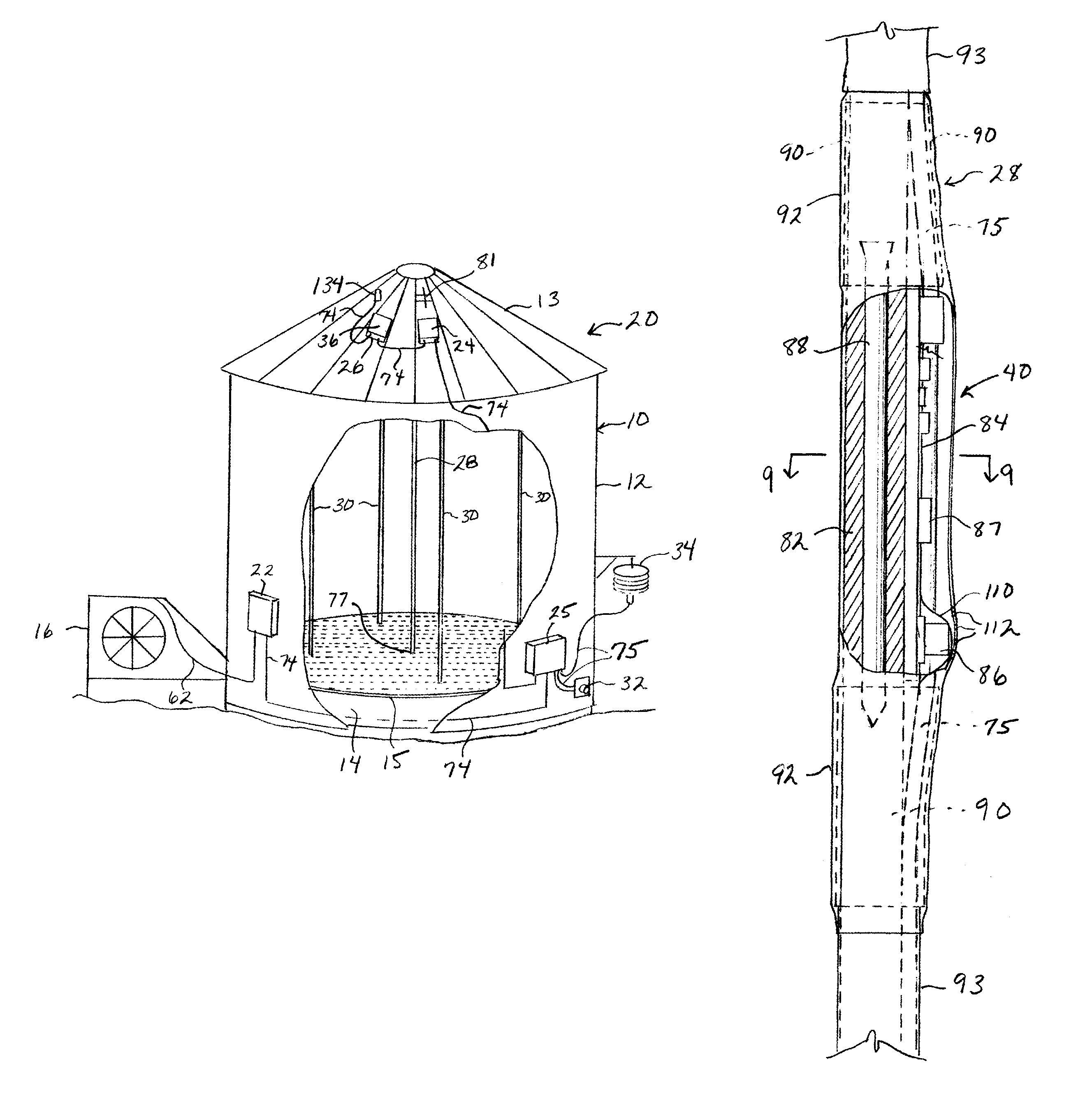
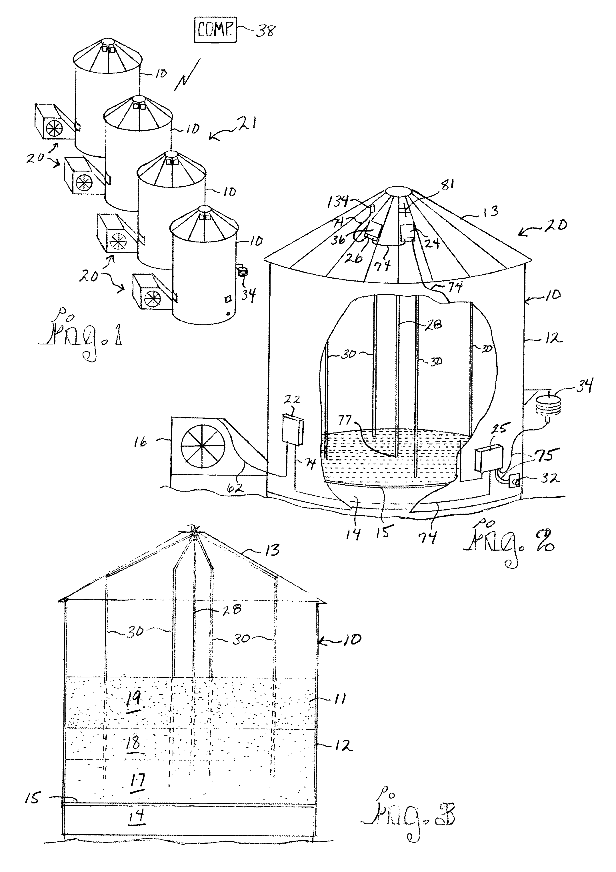
[0030]Now, referring to the drawings and specifically FIGS. 1-3, conventional grain bins 10 for storing harvested grain 11 are shown which have been modified to include a grain drying control system 20 of the present invention. Each bin 10 has a side wall 12, a roof 13 and a plenum chamber 14 formed at the bottom of the bin 10, covered by a perforated floor 15. One or more fans 16 (and / or an optional heater(s), not shown) are installed outside each grain bin ...


PUM


Abstract

A grain drying system includes a master control unit external to the grain storage bin which is preprogrammed with a desirable grain moisture content or EMC. Condition sensor assemblies mounted within the grain bin determine the relative humidity and the temperature of the grain within the grain bin. Also, sensors mounted in the bin's plenum determine temperature, relative humidity and air pressure. A weather station mounted externally of the grain bin determines the outside air temperature and relative humidity. Depending on the conditions determined by the sensor assemblies and the weather station, the master control unit selectively activates the grain bin's drying fan when needed and when it is efficient and effective to do so. A radio or cellular modem allows for communication of the grain's condition. The internal sensor assemblies are preferably secured to flexible cables hung within the grain bin. The cable and rigid rod-like members support the sensors. The sensors may be secured in a spaced relationship along the cable so that the grain condition can be determined throughout the grain bin.

Description

BACKGROUND OF THE INVENTION[0001]An important need exists to dry grain quickly and effectively after harvest to retain maximum quality, to attain a moisture content sufficiently low to minimize infestation by insects and microorganisms (e.g., bacteria, fungi, etc.), to prevent germination and to maximize consumer acceptability of appearance and other organoleptic properties.[0002]Grains are hydroscopic and will lose or gain moisture until equilibrium is reached with the surrounding air. Grains will dry until they reach their equilibrium moisture content (EMC). The EMC is dependent on the relative humidity and the temperature of the air. The relationship between EMC, relative humidity and temperature for many grains has been modeled by researchers: the results have been summarized in Brooker et al. (1974), Drying Cereal Grains, Westport: The Avi Publishing Company, Inc., 265 pp. For instance, EMC's for certain grains are shown in the chart immediately below.[0003]Relative Humidity (%...

Claims


Application Information

Patent Timeline
Patent Type & Authority Patents(United States)
IPC IPC(8): F26B19/00F26B3/00
CPCF26B3/00F26B19/00F26B21/06F26B21/12F26B9/063F26B21/08F26B25/22F26B21/10
Inventor SCHAEFER, JR., DONALD, B.
Owner AGI SURETRACK LLC
Why Eureka
Try Eureka