Pulse width modulated resonant power conversion

a power conversion and pulse width technology, applied in the direction of electric variable regulation, process and machine control, instruments, etc., can solve the problems of low efficiency of portable batteries, load-dependent voltage gain, and power converter circuits developed prior to the present invention that cannot achieve all of these desirable features, etc., to achieve high efficiency and high efficiency

Active Publication Date: 2014-08-19
VIRGINIA TECH INTPROP INC
View PDF10 Cites 27 Cited by
  • Summary
  • Abstract
  • Description
  • Claims
  • Application Information

AI Technical Summary

Problems solved by technology

On the other hand, batteries are often not an economical source of portable power unless they are capable of being recharged using energy which is ultimately generated and distributed as alternating current.
Unfortunately, power converter circuits developed prior to the present invention have not been able to achieve all of these desirable features.
In particular, known isolated DC-DC converters capable of bi-directional power flow have only been capable of providing soft switching over a very narrow load range and have exhibited load-dependent voltage gain even when complicated control schemes and circuitry are employed.

Method used


Image

  • Pulse width modulated resonant power conversion
  • Pulse width modulated resonant power conversion
  • Pulse width modulated resonant power conversion

Examples


Embodiment Construction

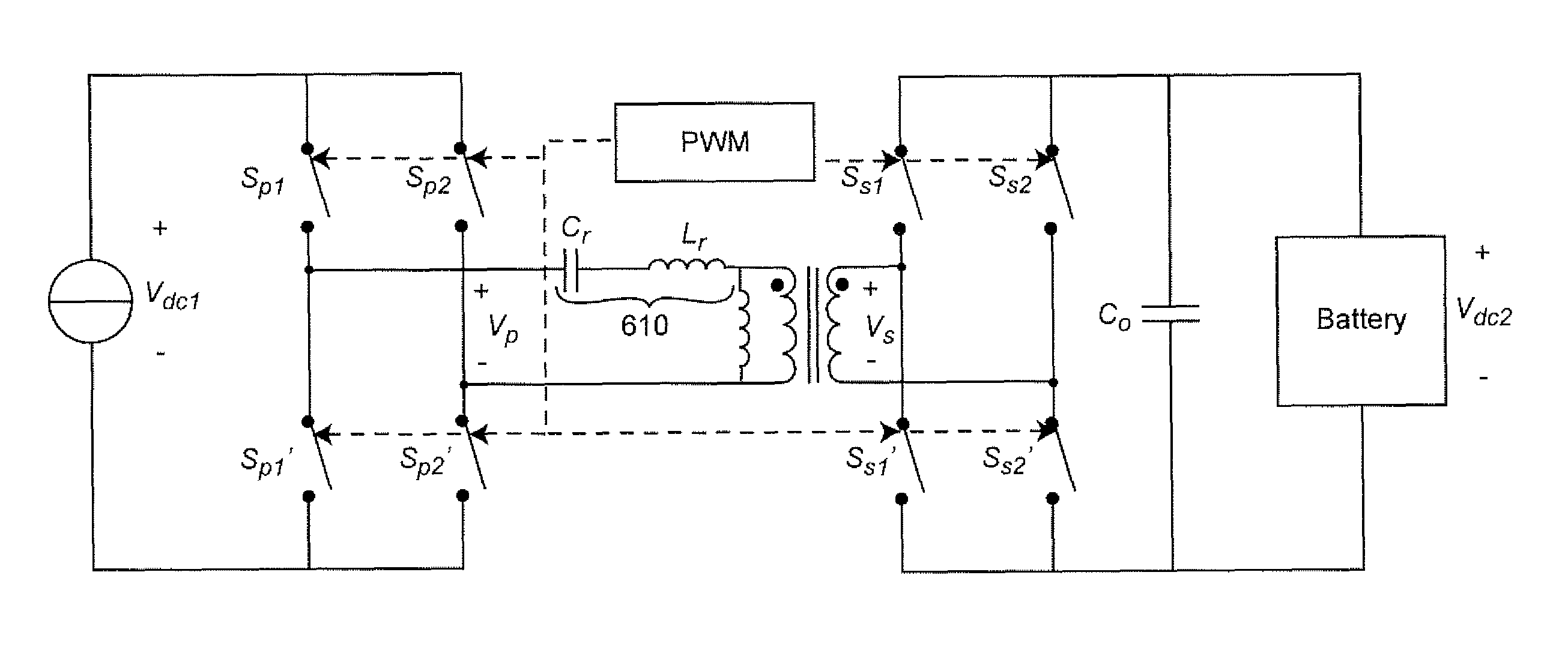
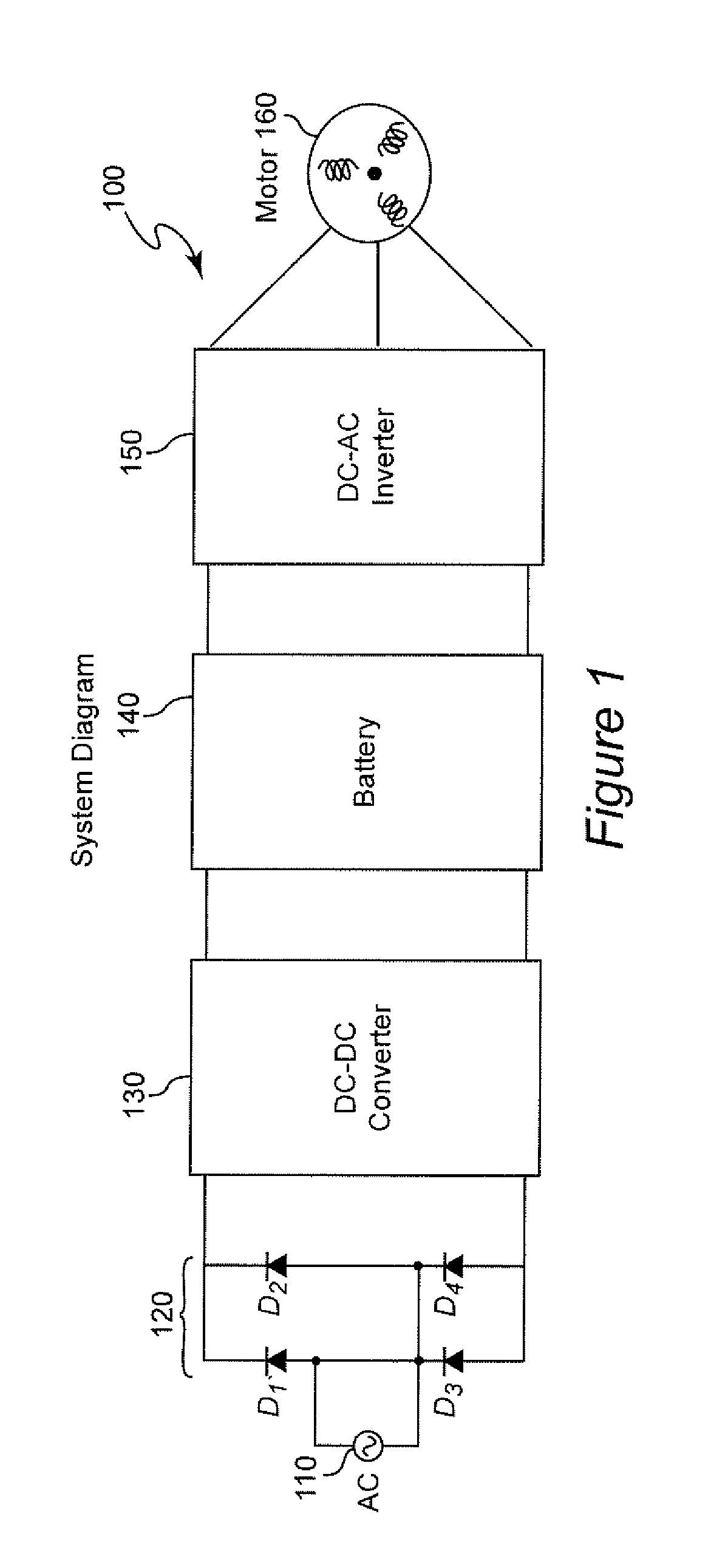
[0028]Referring now to the drawings, and more particularly to FIG. 1, there is shown a high-level schematic diagram of the architecture of a power system 100 as might be used for powering a vehicle. In the system architecture illustrated, while unimportant to the principles of the invention, power is delivered from its ultimate source over, for example, distribution system 110 as AC power. The delivered AC power is then transformed into DC power using a rectifier arrangement 120 which is schematically illustrated as a full bridge rectifier using four diodes but the details of the constitution and configuration of the rectifier arrangement are unimportant to the successful practice of the invention. A filter arrangement, such as a filter capacitor, may be included as part of the rectifier arrangement. The DC power so developed will then be applied to a DC-DC converter 130 which can deliver current at a suitable voltage to a battery 140 for storage. Thereafter, the stored power can be...


PUM


Abstract

A power converter including a resonant circuit is controlled by pulse width modulation (PWM) of a switching circuit to control current in the resonant circuit near the frequency of the resonant circuit (a null-immittance criterion) in order to control current and voltage at the output of the resonant circuit. Further control of voltage can be performed by PWM of a switching circuit at the output of the resonant circuit such that centers of the duty cycles of respective switches for the output of the resonant circuit are substantially synchronized and substantially symmetrical about centers of said duty cycles of respective switches at the input of the resonant circuit. Thus, operation of the converter is substantially simplified by using only PWM, a wide range of input and output voltages can be achieved and the converter circuit can be configured for bi-directional power transfer.

Description

CROSS-REFERENCE TO RELATED APPLICATIONS[0001]This application claims priority of U.S. Provisional Patent Application 61 / 364,954, filed Jul. 16, 2010, which is hereby incorporated by reference in its entirety.FIELD OF THE INVENTION[0002]The present invention generally relates to power conversion and power converter circuits such as may be required for charging batteries of electric vehicles or storing power from intermittently available sources such as power derived from renewable resources and, more particularly, to power converters capable of controlling output voltage through pulse width modulation.BACKGROUND OF THE INVENTION[0003]While alternating current (AC) has long been the standard for distributing power, particularly to loads in fixed locations that may be widely separated from power generation sources where power is continuously generated, there is increasing interest in power systems using so-called renewable resources such as solar and wind power where power generation m...

Claims


Application Information

Patent Timeline
Patent Type & Authority Patents(United States)
IPC IPC(8): H02M3/335
CPCH02M3/33584H02M2001/0058Y02B70/1433Y02B70/1491H02M1/0058Y02B70/10
Inventor THE NGO, KHAI DOANCAO, XIAOWANG, YIN
Owner VIRGINIA TECH INTPROP INC
Why Eureka
Try Eureka