Side access storage rack for cold storage units

a storage rack and cold storage technology, applied in the field of storage racks, can solve the problems of adding manufacturing time and expense to the overall assembly of end plates adding additional weight and materials costs to the side access storage rack, etc., and achieve the effect of limiting any vibration of the shelf and simplifying manufacturing

Active Publication Date: 2014-08-26
THERMO FISHER SCI ASHEVILLE
View PDF33 Cites 9 Cited by
  • Summary
  • Abstract
  • Description
  • Claims
  • Application Information

AI Technical Summary

Benefits of technology

[0008]In one embodiment according to the present invention, a side access storage rack for holding storage boxes within a cold storage unit includes a housing having a top wall, a bottom wall, and a rear side wall extending between the top and bottom walls. The housing defines a storage space accessible through an open front side of the housing. The storage rack also includes a plurality of vertical dividers extending from the rear side wall toward the open front side of the housing, each vertical divider including a front edge and a plurality of divider slots extending rearwardly from the front edge. The storage rack also includes a horizontal shelf including opposing front and rear edges. A plurality of shelf slots extend forwardly from the rear edge and an angled front portion is bent adjacent to the front edge. The horizontal shelf is engaged with the plurality of vertical dividers by sliding the horizontal shelf into the divider slots and sliding the vertical dividers into the shelf slots until the angled front portion of the shelf is wedged into frictional engagement with the divider slots. The frictional engagement holds the horizontal shelf in position such that the horizontal shelf and the plurality of vertical dividers split the storage space into a grid of box receptacles configured to receive the storage boxes. The frictional engagement of the horizontal shelf at multiple locations along its length simplifies the manufacturing of the side access storage rack and advantageously forms a rigid coupling that limits any vibration of the shelf during use of the side access storage rack.
[0014]In one aspect, the horizontal shelf further includes a blocking lip extending upwardly from the shelf at a rear edge. The method further includes inserting the horizontal shelf into the housing until the blocking lip abuts the rear side wall of the housing. The method may also include bending first and second end walls from the flat sheet of material so as to be generally perpendicular to and extending forward from the rear side wall. The first and second end walls are then coupled to the top wall and to the bottom wall such that the housing defines a box-shaped storage space. In another aspect, the method also includes removing the horizontal shelf from engagement with a first set of the divider slots in the plurality of vertical dividers and engaging the horizontal shelf with a second set of the divider slots in the plurality of vertical dividers. This repositioning of the shelf causes a reconfiguration of the vertical height of the box receptacles formed in the storage space.

Problems solved by technology

This additional machining adds manufacturing time and expense to the overall assembly of the side access storage rack.
When the projecting tabs are formed in separate end plates connected to the first and second end walls, the end plates add additional weight and materials cost to the side access storage rack.
Furthermore, correctly snapping the shelves 300 into position requires additional assembly time.
Consequently, the horizontal shelves 300 are prone to small vibrations resulting at least in part from this resiliency and also in part from the long lengths between support points when the side access storage rack is moved.
Even though the horizontal shelves 300 are securely held within the housing, the vibrations may provide the undesirable impression that the side access storage rack is unstable or poorly assembled.

Method used


Image

  • Side access storage rack for cold storage units
  • Side access storage rack for cold storage units
  • Side access storage rack for cold storage units

Examples


Embodiment Construction

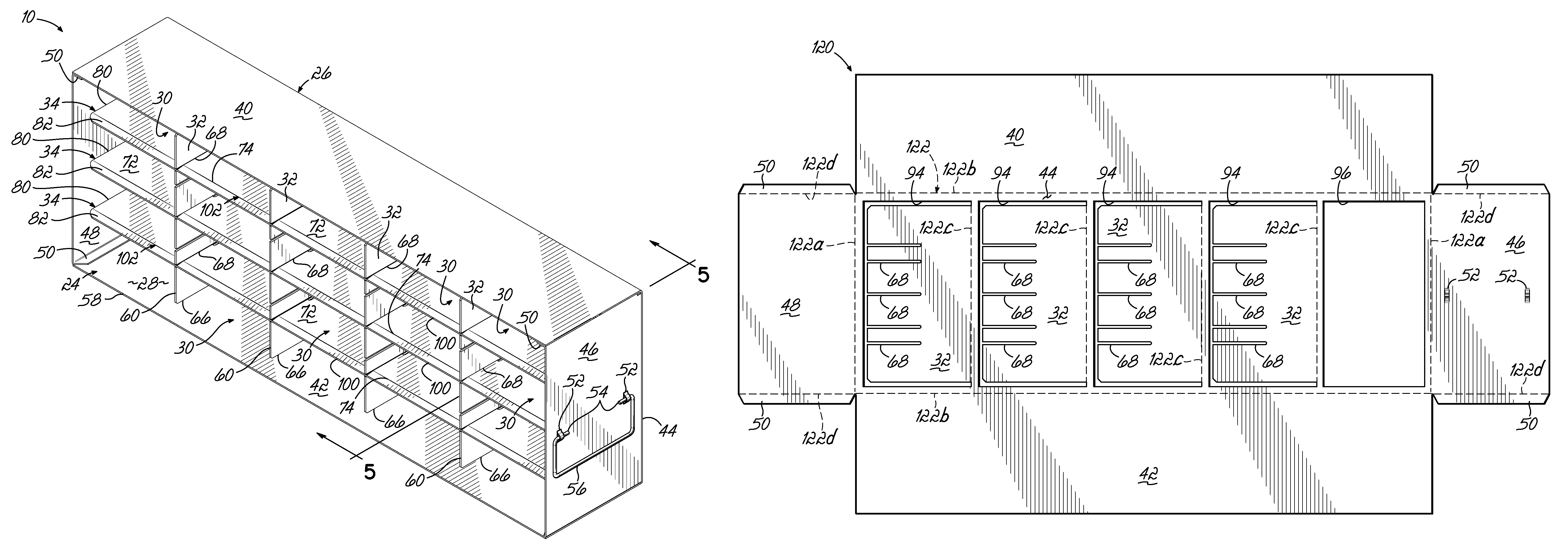
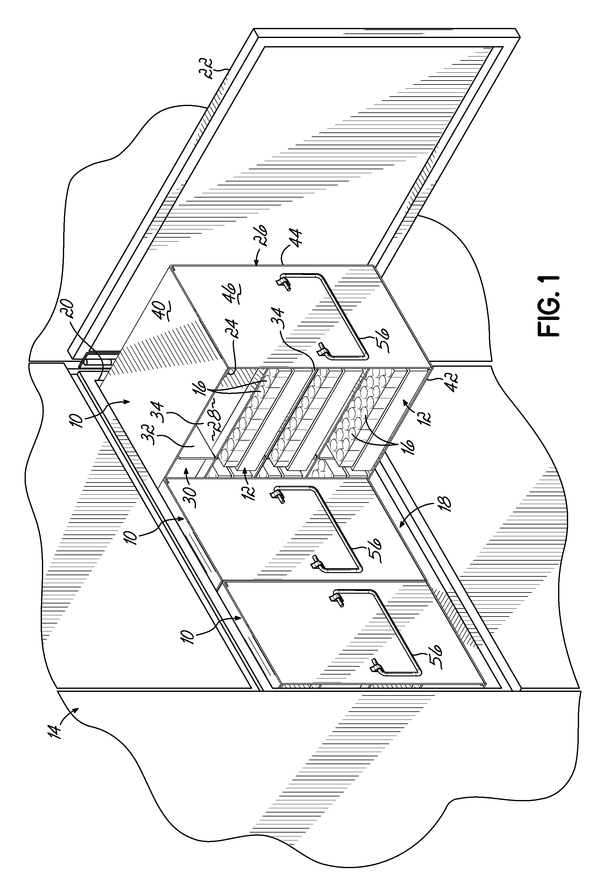
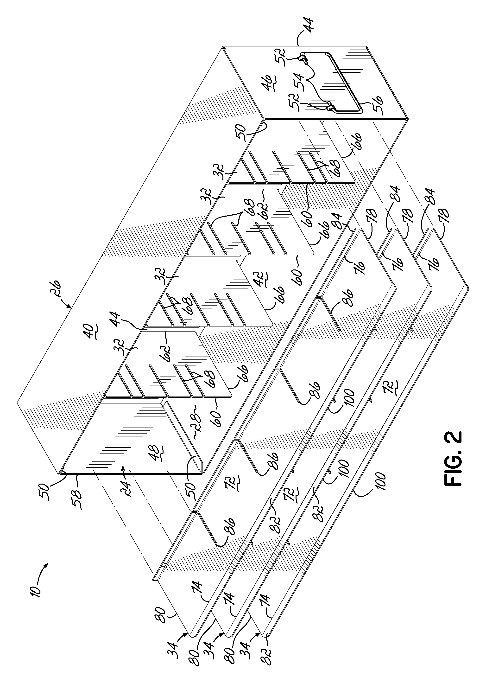
[0025]With reference to the figures, and more specifically to FIGS. 1 through 6, an exemplary embodiment is shown of a side access storage rack 10 used to hold storage boxes 12 (alternatively, “micro plates”) within a cold storage unit 14 or a similar cryogenic vessel. Although the term “cold storage unit” is used throughout the specification, it will be understood that the side access storage rack 10 disclosed herein may be used with any type of cooling device, including refrigerators, freezers, and cryogenic vessels of any variety, collectively referred to hereinafter as “cold storage units.” The storage boxes 12 typically contain a grid (not shown) or other internal structure for receiving and orienting a plurality of vials 16 or tubes filled with biological samples in an array. However, the storage boxes 12 may be sized to receive other types of containers for biological samples. As shown in the environment of the cold storage unit 14 in FIG. 1, the storage rack 10 is configured...


PUM

PropertyMeasurementUnit
temperaturesaaaaaaaaaa
vertical heightaaaaaaaaaa
heightsaaaaaaaaaa

Abstract

A cold storage unit includes a side access storage rack for holding storage boxes. The storage rack includes a housing with a top wall, a bottom wall, and a rear side wall extending between the top and bottom walls to define a storage space. The storage rack also includes a plurality of vertical dividers extending from the rear side wall and a horizontal shelf configured to be engaged with the plurality of vertical dividers to split the storage space into a grid of box receptacles for the storage boxes. The horizontal shelf includes an angled front portion that is bent and is configured to frictionally engage divider slots in the vertical dividers to thereby hold the horizontal shelf in position with respect to the housing. This frictional engagement simplifies manufacturing and improves the functionality of the storage rack.

Description

FIELD OF THE INVENTION[0001]The present invention relates generally to storage racks and, more particularly, to side access storage racks used with cold storage units such as upright freezers.BACKGROUND OF THE INVENTION[0002]Cold storage units such as freezers and dewars are used for various purposes, including the storage of biological samples over short and long periods of time. For example, biological materials for transplantation such as blood, tissue, or plasma may require storage for short periods of time before use. In another example, biological cells such as DNA samples may be stored for longer periods of time. Conventional cold storage units may be cooled by mechanical refrigeration circuits or by other methods, including the provision of liquid nitrogen (“LN2”). One type of cold storage unit used to store biological samples is known as an “ultra-low temperature freezer” (“ULT”), which is used to cool its inner storage chamber to relatively low temperatures such as about −...

Claims


Application Information

Patent Timeline
Patent Type & Authority Patents(United States)
IPC IPC(8): A47B96/04A47B87/00A47B43/00
CPCB23P11/02F25D23/02F25D25/02A01N1/02A01N1/0242A01N1/0257A47B47/02A47F3/0404B01L9/00F25D25/024G01N1/00G01N2035/0498Y10T29/49863B01L7/50B01L2200/022B01L2200/028
Inventor WARD, DENNIS D.HUTCHINSON, JOHN P.SCHOTT, BRIAN E.
Owner THERMO FISHER SCI ASHEVILLE
Why Eureka
Try Eureka