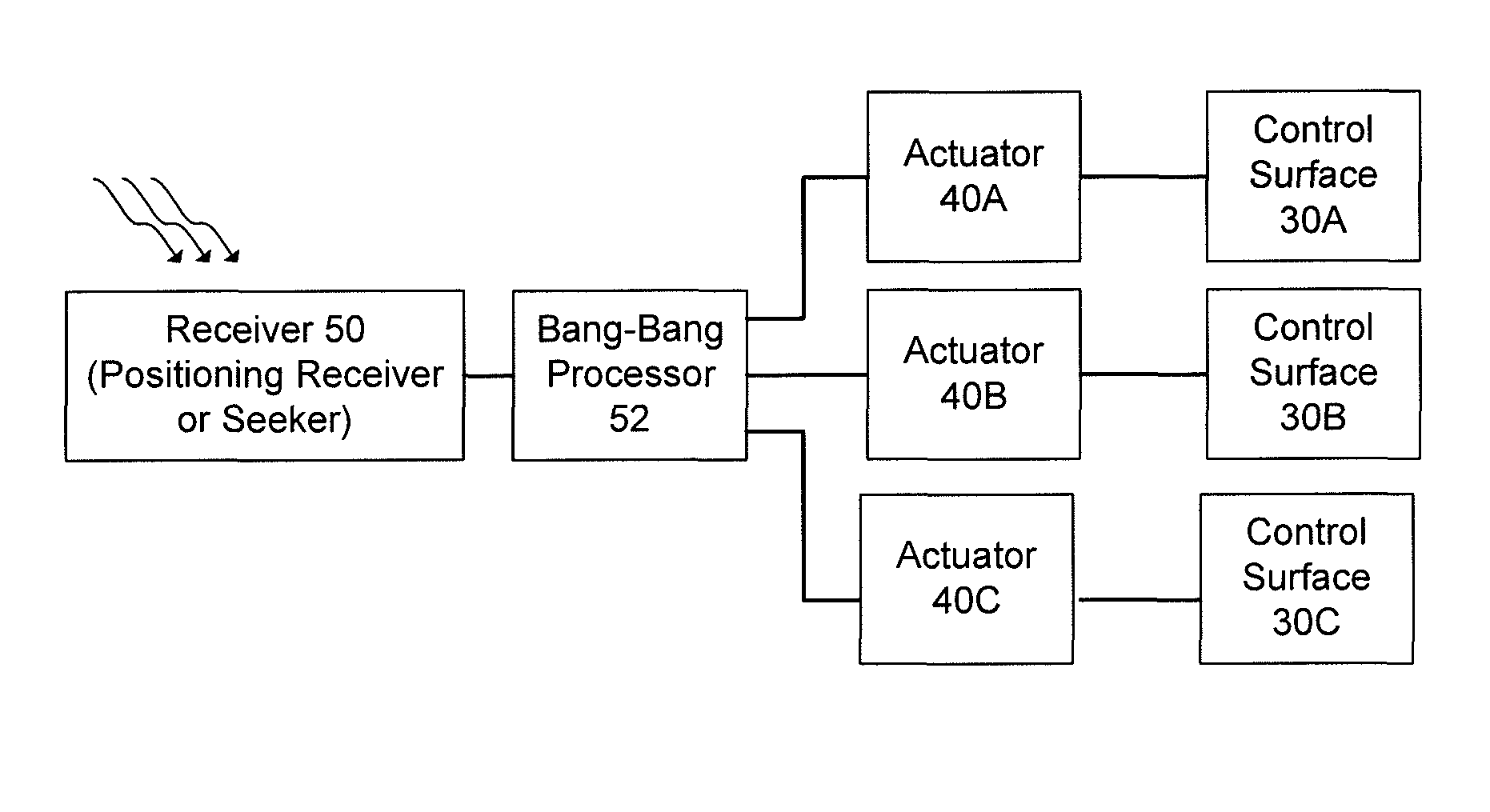
Bang-bang control using tangentially mounted surfaces

a technology of tangential mounting surfaces and control systems, applied in direction controllers, instruments, weapons, etc., can solve the problems of difficult to utilize such advanced control and actuation systems in a small form factor in a low-cost projectile, system is also expensive, and the 3-axis proportional control actuation system is bulky. , to achieve the effect of minimizing costs, reducing the size of the form factor, and limited engagement rang

Active Publication Date: 2014-08-26
RAYTHEON CO
View PDF51 Cites 4 Cited by
  • Summary
  • Abstract
  • Description
  • Claims
  • Application Information

AI Technical Summary

Benefits of technology

[0003]Several challenges exist with implementing a small form factor projectile having a limited engagement range. Such challenges include small form factor components and minimizing costs. It is difficult to utilize such advanced control and actuation systems in a small form factor in a low cost projectile. A 3-axis proportional control actuation system is bulky, as it requires 3 motors, gear trains, and canard storage, for example. Such a system is also expensive as it requires micro machined parts, close tolerances, and a high part count, which may be considered overkill for a near-ballistic flight.

Problems solved by technology

Several challenges exist with implementing a small form factor projectile having a limited engagement range.
Such challenges include small form factor components and minimizing costs.
It is difficult to utilize such advanced control and actuation systems in a small form factor in a low cost projectile.
A 3-axis proportional control actuation system is bulky, as it requires 3 motors, gear trains, and canard storage, for example.
Such a system is also expensive as it requires micro machined parts, close tolerances, and a high part count, which may be considered overkill for a near-ballistic flight.

Method used


Image

  • Bang-bang control using tangentially mounted surfaces
  • Bang-bang control using tangentially mounted surfaces
  • Bang-bang control using tangentially mounted surfaces

Examples


Embodiment Construction

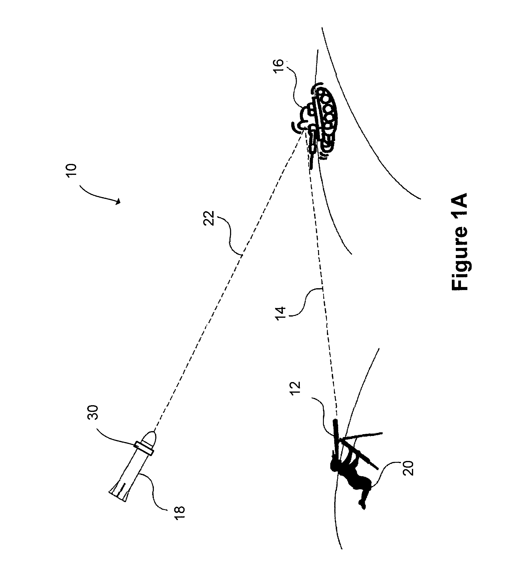
[0020]FIG. 1A shows schematically a system 10 according to one aspect of the present invention. The system 10 includes a laser illuminator 12 for directing a laser beam 14 at and illuminating a target 16 and a guided projectile 18 having a target seeker device that detects the reflected electromagnetic radiation from the target 16 and the guided projectile 18 is operable to change course in flight based on the detected electromagnetic radiation 22 to strike the target 16. In one embodiment, an operator 20 directs the laser illuminator 20 at the target 16. The operator 20 may be positioned in any location (e.g., on the ground, in an aircraft that launches the guided projectile 18, etc.). The guided projectile 18 may be fired from a launcher (not shown) or another source and the target seeker device in the guided projectile 18 detects the reflected electromagnetic radiation 22 from the target by means of a detector. The guided projectile homes on such reflected illumination by means o...


PUM


Abstract

Control surfaces secured tangentially to a round projectile, such that the lift force generated by the control surfaces is generated through the projectiles centerline. This eliminates the need for an opposing fin to counter roll moment. Sizing the control surfaces to form an equilateral triangle gives each panel equal span, and enables the force generated by two panels to be equal and opposite to that of the opposing panel. The end effect is that each panel only has two active states (neutral and positive deflection). Thus, a solenoid and a return spring may be used to control the canards. Additionally, the control panels may fold along the surface of the projectile, which frees up internal volume and minimizes the length of the control section.

Description

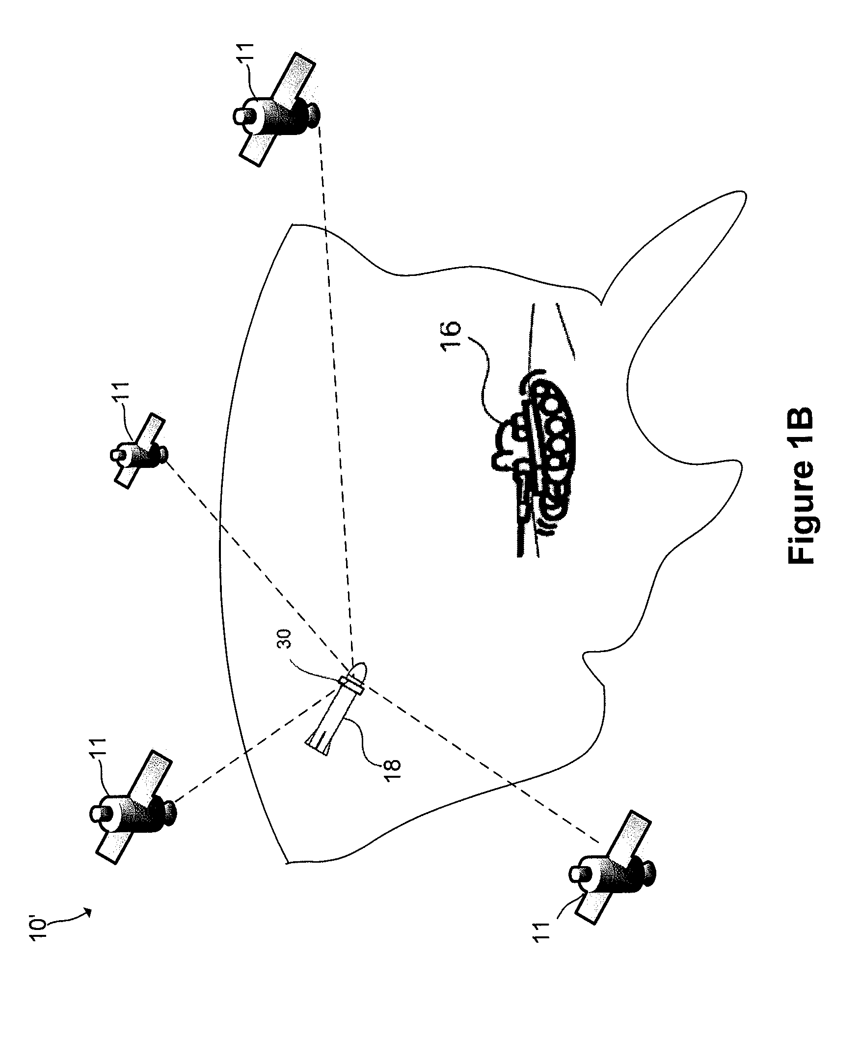
TECHNICAL FIELD[0001]The present invention relates generally to a system and method for bang-bang control for a guided projectile and, more particularly to a system and method for generating equally spaced resultant force vectors using a bang-bang control actuation system with a plurality of control surfaces mounted tangentially around a surface of the projectile.BACKGROUND OF THE INVENTION[0002]Laser-guided projectiles generally use a laser illuminator to mark (e.g., illuminate, “paint”, etc.) a target. The reflected laser light from the target is then detected by the seeker head of the weapon, which sends signals to the weapon's control fins to guide the weapon toward the designated target. Global positioning system (GPS) guided projectiles generally rely on GPS or other location based satellites to guide the GPS-guided projectile to the designated target. It is common for laser-guided projectiles and GPS-guided projectiles to include advanced control and actuation systems to dire...

Claims


Application Information

Patent Timeline
Patent Type & Authority Patents(United States)
IPC IPC(8): F42B10/62F42B15/01F42B15/00F42B10/00
CPCF42B10/00F42B15/01F42B15/00F42B10/62
Inventor BLAKE, JESSE H.MURPHY, MATTHEW G.
Owner RAYTHEON CO
Why Eureka
Try Eureka